When you say "Stock EI cores" you must take into consideration the quality of the iron being used back then.
Your typical EI iron that was used for power transformers was not the same as what was typically used for Audio transfomers of decent quality.
Today these better types of iron are more commonly available and used more often than not because they make the transformer more efficient as efficiency is the name of the game these days.
Very good Points Bolserst!!
Lately I have been think about using bridged amps with lower transformation ratio in order to get that higher voltage swing that is needed while not having to dip very far below the 4 ohm range.
It makes little difference on how much power is actually used as it is nearly the same only the impedance is shifted.
I found that I can get 40Vms at a 300Hz saturation point.
At 40Vrms I get 4500Vp-p out of the AS-1206(m) and this actually enough to make my little panel really sing.
With a bridge amp this would be pushing the voltage levels near past the capabilities that the panel was designed for.
Basically were I had left off when it burned up, only I use using a 1:256 ratio and less than a 20Vrms input.
Since the panel was naturally crossed over at 600Hz or so this makes 80V quite a feasible voltage limit using just one core without demanding an incredible amount of current from the amplifier.
Next on my list is to Build a PA200 chipamp inorder to handle the low impedance dips and see how it will perform.
At only 20Vrms this is still 28Vpeak and is more than what I was using, when I left off.
Then I will build a bridged version in order to double up the voltage and see if I can get away with using just the one AS-1206 core.
I am also hoping that this will work using my PE cores with the 10 turn winding at 1:64 ratio or somewhere in between with a 15 turn at 1:42.6 ratio or so.
Of course running at a lower level will help to extend my lowest crossover point.
With the little panels at 105db it takes everything the little 5.25" woofer can muster up to compete against them anyhow.
All that is required to exceed this is 20Vpeak at 1:256 or 5Kv peak with a 7Kv Bias voltage.
I will build a larger panel soon that I can compare the differences myself and see how it pans out.
jer")
Your typical EI iron that was used for power transformers was not the same as what was typically used for Audio transfomers of decent quality.
Today these better types of iron are more commonly available and used more often than not because they make the transformer more efficient as efficiency is the name of the game these days.
Very good Points Bolserst!!
Lately I have been think about using bridged amps with lower transformation ratio in order to get that higher voltage swing that is needed while not having to dip very far below the 4 ohm range.
It makes little difference on how much power is actually used as it is nearly the same only the impedance is shifted.
I found that I can get 40Vms at a 300Hz saturation point.
At 40Vrms I get 4500Vp-p out of the AS-1206(m) and this actually enough to make my little panel really sing.
With a bridge amp this would be pushing the voltage levels near past the capabilities that the panel was designed for.
Basically were I had left off when it burned up, only I use using a 1:256 ratio and less than a 20Vrms input.
Since the panel was naturally crossed over at 600Hz or so this makes 80V quite a feasible voltage limit using just one core without demanding an incredible amount of current from the amplifier.
Next on my list is to Build a PA200 chipamp inorder to handle the low impedance dips and see how it will perform.
At only 20Vrms this is still 28Vpeak and is more than what I was using, when I left off.
Then I will build a bridged version in order to double up the voltage and see if I can get away with using just the one AS-1206 core.
I am also hoping that this will work using my PE cores with the 10 turn winding at 1:64 ratio or somewhere in between with a 15 turn at 1:42.6 ratio or so.
Of course running at a lower level will help to extend my lowest crossover point.
With the little panels at 105db it takes everything the little 5.25" woofer can muster up to compete against them anyhow.
All that is required to exceed this is 20Vpeak at 1:256 or 5Kv peak with a 7Kv Bias voltage.
I will build a larger panel soon that I can compare the differences myself and see how it pans out.
jer
Last edited:
An Dont take what i am saying the roungway....It know ones place to tell me are anyone what for them to use...your all doing great work for all to see...
For years all i have heard..An read....is the Acoustat stepup tranfourmers were junk!
An we can get better sound on the Acoustat panels with better iorn...
An the ML Tranfourmer are low cost junk..an we can do better...
An i have had the Simmit here an the setup troi Tranfourmer in the Over $10k looks just like 1 size wize the Antek...an some say these are great sounding speakers...
Funny thing is i have had SoundLab,Acoustats,ML, Quad,KLH,JanZen,ESL an with work thay all sound great with stock EI cores ....I like all i gess just wont better.....thanks for all your time...
At least Quad uses c-cores (esl-57 and esl-63 )
A costum made esl transformer cost about €100-€200 so still a fraction of all the other costs.
Hi chaps,
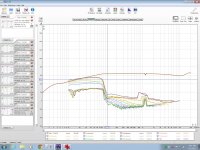
I have tested 3 transformers and here are the results. All are pretty similar.
The transformers all had 2x 6V windings connected in parallel and used for the input. Then 2x 115V windings connected in series and used for the output.
I fed 10V input and got near 350V output.
I connected an attenuator at the output of the TX to feed my soundcard. This was 10Meg in series and 1Meg in parallel.
All impedance measurements were made without the attenuator connected, except this first one which shows both.
Block RK63/6


Nuvotem 91227-P2S2


Noratel TA030/06 (Ordered Multicomp but got this)


The reason the impedance plots look jagged is because I was feeding it directly from the headphone output of my soundcard. It's probably drawing too much current, but IME the plots are pretty accurate.
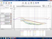
I noticed that all distortion plots looked similar, and the top end impedance is very low, so I also tried each with a 1.2R resistor in series with the input.
Block

Nuvotem

Noratel

I thought this would improve distortion in general, but while HF distortion does seem to reduce, interestingly 2nd harmonic seems to increase in the lower range.
Finally, I tired the Block and Noratel with the outputs in series to give twice the step-up. I tested this with 5V input and about 350V output.
Block and Noratel in Series (no series resistor at input)

I have tested 3 transformers and here are the results. All are pretty similar.
The transformers all had 2x 6V windings connected in parallel and used for the input. Then 2x 115V windings connected in series and used for the output.
I fed 10V input and got near 350V output.
I connected an attenuator at the output of the TX to feed my soundcard. This was 10Meg in series and 1Meg in parallel.
All impedance measurements were made without the attenuator connected, except this first one which shows both.
Block RK63/6


Nuvotem 91227-P2S2


Noratel TA030/06 (Ordered Multicomp but got this)


The reason the impedance plots look jagged is because I was feeding it directly from the headphone output of my soundcard. It's probably drawing too much current, but IME the plots are pretty accurate.
I noticed that all distortion plots looked similar, and the top end impedance is very low, so I also tried each with a 1.2R resistor in series with the input.
Block

Nuvotem

Noratel

I thought this would improve distortion in general, but while HF distortion does seem to reduce, interestingly 2nd harmonic seems to increase in the lower range.
Finally, I tired the Block and Noratel with the outputs in series to give twice the step-up. I tested this with 5V input and about 350V output.
Block and Noratel in Series (no series resistor at input)

Last edited:
So, any comments?
I can see the effect of the winding capacitance causing the HF to go up a little and the impedance to drop. Adding the series resistor smooths the FR and increases the impedance slightly but makes 2nd harmonic higher in the mid-range. Why?
What have I learned? Well I think the amp having a hard time driving the impedance is probably the main cause of distortion rather than the TX itself, especially at HF.
It makes me think okay that was much better than expected from a mains TX, but perhaps I should try a valve amp output TX next.
My plan is to run a panel from about 300Hz up to 10KHz, so these could be suitable but if I can get better that would be nice.
Hi,
Take a look to this page(especially fig. 11.5) :
Transformers Part 2 - Beginners' Guide to Electronics
As you can see both Lp(primary inducatance) which is non-linear as well as Rp(iron loss) components are in parallel with load. That means if Ll(leakage inductance) and Rw(series resistance) were zero Lp & Rp would have no effect on distortion.
By increasing Rw both non-linearity of core inductance as well as iron losses cause the voltage to fluctuate at load more, causing increased distortion.
Regards,
Lukas.
So, any comments?
I can see the effect of the winding capacitance causing the HF to go up a little and the impedance to drop. Adding the series resistor smooths the FR and increases the impedance slightly but makes 2nd harmonic higher in the mid-range. Why?
Thanks Lukas that makes more sense now.
Actually I had meant to post this all in the thread Toroidal Transformers for ESL Panels would a mod kindly move it over there? It makes more sense for people searching later.
Actually I had meant to post this all in the thread Toroidal Transformers for ESL Panels would a mod kindly move it over there? It makes more sense for people searching later.
Very Good !!!
I many of my tests I have found the same jagged irregularity in some of the curves and found them to be random and intermittent.
I had found this to be the fault of my motherboards sound card.
My good out board sound cards don't do that and produce clean curves.
You can do a Loop back test to verify this.
I was pretty much stuck using my motherboard sounds at the time.
But here are a few examples of the same issues I had as well.
The other thing is that if you don't use a buffer in between the divider and the sound card input you will get non-linearity's as as the low impedance of the capacitor input of the sound card input changes and is not driven with enough current from the output of your high impedance voltage divider.
Else your curves look pretty good.
Very similar to my first curves then I found the issue I had explained using Visual Analyzer and made a buffer and now they are clean and accurate.
http://www.diyaudio.com/forums/software-tools/212908-exploring-visual-analyser-va-3.html#post3669921
Be sure that you use an opamp the is unity gain stable if you use a unity gain buffer.
I had found the sometimes the opamp I was using would set it self into oscillation and it took me a while to find this as it didn't happen all of the time.
The photo of the Holm sweep may have been from using my GINA24 card in my other machine and it is very clean.
I will see if I still have the plots I did using the other cards.
I was having a hard time trying to figure out if it was the sound card or the software that was causing the glitches.
In my earlier post using SimpleS I had the same issues and they went away when I switched to a better sound card in a different machine and is why the curves were smooth and doing the same test with the same Transformer on my new motherboard's sound system and produced dirty curves again.
Here is the thread were I described the weird issues I was having too,
A TEST JIG FOR FINDING ESL STEP-UP TRANSFORMER PARAMETERS
The reason I was stuck was that my good sound cards (Phillips PSC706, Creative X-Fi and Gina24) don't work in my new machine with Win7.
What are the wattage ratings of your three samples, or, are their core sizes the same or different?
The First and last photos should be close to what your results should be with out all of the noise.
Cheers !!!
jer
Attachments
I used an M-Audio FastTrack Ultra. In the distortion and FR tests this was feeding an Alesis RA500 amp (one channel not bridged) and back to the M-Audio line input via attenuator.
The impedance test was directly fed from the M-Audio.
I don't really follow your comment about the capacitor input of the soundcard? Why will it help to have a buffer, since the soundcard input is buffered already? I was getting near 1V into my soundcard.
I should add, I have used this card to do distortion tests before and it produces clean curves. Here is a loop-back of the soundcard (no power amp).

Last edited:
Most sound cards have a capacitor at the input.
The input impedance changes with frequency and as it is in parallel with the bottom resistor of the voltage divider with respect to ground.
Do a Loop back test with your amp connected to such a divider of say 10:1 or 20:1 or higher with the input to the sound card taken off of the divider and see how it compares to with signal coming right out of the amp without it.
Just be very careful that you don't go over the voltage input rating of your sound card, typically stay below 5Vp-p to be safe, YMMV.
You probably won't need to do the test without it, if, your amp is of good quality and has a flat response.
This is how I had discovered this, as I wanted to do a loop back reference and found the FR had changed from measuring directly out of the amp itself compared to using the voltage divider knowing that my amp is fairly flat.
Adding the buffer corrected this.
Your card may be different and may very well be going directly into an opamp, instead of going into a capacitor and then into an opamp.
A unity gain buffer has a very high input impedance at the + input of an opamp and doesn't impose any changing load on the bottom of the divider.
This was also an issue when I was using my DVM and I discovered that I was getting errorneous readings as the meters input impedance was much lower and in parallel with the bottom resistor thus changed the value of my Calculated Division Ratio when I started measuring high voltages while I was designing my Variable HV Bias supply.
The output(High) impedance of the divider needs to feed an even higher input impedance, a unity gain buffer (current gain) is able to have enough current to properly feed the low impedance input of the sound card without having any voltage droop of the signal you are trying to measure and/or without loading the divider changing the division ratio.
A capacitors resistance gets lower as the frequency get higher.
This calculator may be able to help you as it also includes the input resistance a the measuring circuit,
Voltage Divider
jer
Oh, now I get you! I had thought you are talking about the DC blocking cap but you mean the RF filter cap usually about 200pF. Also yes, of course the output of the voltage divider is about 1Meg so it will not feed the 10K input of my soundcard well. Can't believe I didn't think of that, usually I use a much lower value voltage divider for recording the output of amps, like 1K output Z.
I shall build a high-Z buffer and try again!
I shall build a high-Z buffer and try again!
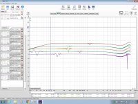
Okay I have built a TL074 unity gain buffer and taken measurements from that. I had no input Z setting resistor on the buffer, so it would present a very high impedance and bias current would be drawn through the voltage divider at the transformer end.
These are the results same settings as before - 10V input.
Block

Noratel

Nuvotem

So in this case we can see that the Block TX seems to have lowest distortion. This is probably because the Nuvotem and Noratel are both 30VA and the Block is 60VA.
I then tried the Block and Noratel in series, and halved the input voltage.

One thing I find a little confusing with these tests is that when I do an FFT I can see quite high content of mains harmonics. The amp of course produces some, but if I measure the amp direct they are quite low compared to the signal. After going through the TX step-up and attenuator they seem much higher compared to the signal. I tried fiddling with grounding but it made little change.
Anyway, I am hoping to build a panel for 300Hz-10KHz. I thought 30VA would be enough, but it looks like maybe I need a much bigger core? To tell the truth though, a 200VA core from Farnell or similar would cost about £90 inc postage. At that price the attraction of using a power toroid is gone and I might as well buy a specialised ESL TX from Sowter at £130.
Last edited:
Very Good !!
Those curve look much better.
From about 300hz (the point of saturation) I get about .5% thd and then it drops to about .1% and then by the time it gets to 500hz or so, and above 1Khz it is quite low typically .04% or lower.
Depending on my voltage level and whether or not I have the software properly calibrated for the level that I am testing, I have gotten readings as low as .004% above 1Khz at full power, and that is the limit of my sound cards THD.
At this point I am basically measuring my amps THD (Crown DC300a).
In some of my earlier measurements, A larger core does give a bit lower THD for the lower frequency's up until saturation.
I have only to sizes to work with an Antek 120watt and some 210watt core that I have a bunch of.
I had stacked as many as Six of those 210watter's before and it showed that the more iron you have the better the sine wave looked at the lower frequency's and that was without reaching core saturation.
I didn't have an FFT system or THD measuring system setup back then.
Even .5% THD at the onset of core saturation is better than what most dynamic drivers can do.
In all of my last tests my main focus was on finding the absolute limits of the transformers and panel materials.
In my next phase I plan to focus more on the range for quality and reliability.
Antek has their 100 watt cores for $18 and the 25 watt cores for $11, but I have no idea what it would cost you for the shipping though.
As long as you are above 300Hz the smaller cores are just fine.
My tests were at 40Vrms max but typical listening levels would not be above 5Vrms to 10Vrms (depending on your panels size, bias voltage and transformation ratio) except for the occasional transient peaks.
And of course, Your listening habits.
I have issues with the mains at the lower levels of my test data too.
This for me is caused by the interference around me and ground loops.
the best I could do to reduce it at times is a about another 6db from -82db to -89db or so.
The rest of my noise floor is at least -115db to -118db or better.
This is after I had tried to re-arrange my power cables as my reading before was about -68db to -74db!!!
And that is with all of my CRT's off !!
That is just going from my signal generator to the input with no signal, If i disconnect the cable and/or short the inputs then all I get is my very flat noise floor.
I figured out that this noise as somewhere around the 100uv or less range, not very much but it is a big deal.
These transformers also act as antenna's as I can see signals form nearby radio stations when I hook them up to my scope.
FWIW
jer
P.S. Great Tests by the way, Thanks for sharing !!!!
Last edited:
Thanks for the info Jer
Yes I found if I shorted the input to my buffer it was very quiet. With the power amp disconnected from the TX I was still getting some noise and with the amp connected it was more too. Like you say I think the TX picks up noise from the air as do the crock-clips. I was feeding the TX from about 3 meters of cable so that can pick up stuff and be stepped-up.
Does anyone have comparative measurements for a more specialised TX? Jer have you tried push-pull amp outputs TXs? I might borrow those from my friends KT88 amp and see what they do. Not sure what the ratio is though.
The attraction of an ESL is low distortion for me and the ability to make it concentric with the tweeter section. I'm considering making a panel as an alternative to a pair of ATC domes so it will really need to perform to kick those out.
Again I'd ask a mod to move this data to the ESL toroid thread.
Last edited:
I have one PP OPT from a Knight PA amp the had EL34's in it.
I tested it back in 2010 with the method's that I did know back then and I was not impressed.
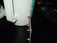
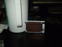
Although it did work great for my Micro ESL headphone driver (See Pic's).
The ratio for one was way too low to be used with my Little Panel and I didn't want to risk burning it out with the high voltages as it is the only OPT that I have and the amp still works.
I had a pair of 6V6 opt's that I used when I built my first set back in 2003 but they eventually gave out due to the high bias voltages that I was pushing.
But they sure sounded great (for awhile..He,he,he,he)!!!!
I had the same idea as you with my little panel (3.25" x 9.75") that "Hey this thing should be able to at least out perform my Midrange and tweeters!!" and it DID !!!
But I ended up burning it up before I got to put it in finally service.
But the pair cost me less than $10 to make and I have plenty more material.
When built properly these thing will scare you out of the room!!!!
When listened to properly they will engulf you into what you are listening to!!!!!!
I haven't listen to them in stereo since about 2004 when my original OPT's finally quit working.
Since 2010 when I revived my little panels I only used one pnal at a time to do all of my testing and to learn understand the characteristics and what their flaws were in order to improve upon them in the next build.
But I was still amazed listening to just one panel when I finally got it to mate properly with one of my little 5 1/4" woofer and with a 8" sub driver as well.
Just incredible !!!
And I have a set of Apogee's Duette's that I am accustomed to listening too!
The detail that I could hear using just one channel was more than what I could imagine hearing in stereo.
Coloration you say?
There is none no matter what size panel you choose to build they all sound the same with the exception of the low end extension form wider panels, but the wider the panel the more the high frequency's focus into a beam.
This part is true for any driver and is a function of physic.
As always there are compromises to be made.
I was able to get my little panel as loud as +105 db at 1 meter with just a moderate 80watt amplifier before they succumbed to failure form over voltage when I took them to the next level that they had been before.
Before I didn't have an SPL meter at the time but it took me out of the room using my DC300a.
But the failure I had is an easy fix now that I know the limitations of the materials that I am working with.
Besides those where absolute maximums and would they never reach those limits under normal use.
You can build them any size you want but for an application such as you are describing you may want to go with some thing small.
Something along the means of my current and earlier little panels or even something similar to this current build,
http://www.diyaudio.com/forums/planars-exotics/246529-louvre-panel-solvent-acoustat.html#post3762887
The trick is that these are narrow and they don't beam nearly as bad as a wide panel will.
If you use the proper materials and use a higher bias voltage with a fairly high step-up ratio of at least 1:150 or so if not higher ( I have used as high as 1:256) these little panels will knock your socks off!!
And, so will a larger panel as well even more so due to the increased surface area.
I have some Perforated material that I have finally decide to make two 4 foot long by 5" wide panels for use as Midrange/Tweeter for my Big system, as I am tired of blowing out and replacing the dynamic drivers and the last set has been blown out again and will never be replaced again!!!
jer
I tested it back in 2010 with the method's that I did know back then and I was not impressed.
Although it did work great for my Micro ESL headphone driver (See Pic's).
The ratio for one was way too low to be used with my Little Panel and I didn't want to risk burning it out with the high voltages as it is the only OPT that I have and the amp still works.
I had a pair of 6V6 opt's that I used when I built my first set back in 2003 but they eventually gave out due to the high bias voltages that I was pushing.
But they sure sounded great (for awhile..He,he,he,he)!!!!
I had the same idea as you with my little panel (3.25" x 9.75") that "Hey this thing should be able to at least out perform my Midrange and tweeters!!" and it DID !!!
But I ended up burning it up before I got to put it in finally service.
But the pair cost me less than $10 to make and I have plenty more material.
When built properly these thing will scare you out of the room!!!!
When listened to properly they will engulf you into what you are listening to!!!!!!
I haven't listen to them in stereo since about 2004 when my original OPT's finally quit working.
Since 2010 when I revived my little panels I only used one pnal at a time to do all of my testing and to learn understand the characteristics and what their flaws were in order to improve upon them in the next build.
But I was still amazed listening to just one panel when I finally got it to mate properly with one of my little 5 1/4" woofer and with a 8" sub driver as well.
Just incredible !!!
And I have a set of Apogee's Duette's that I am accustomed to listening too!
The detail that I could hear using just one channel was more than what I could imagine hearing in stereo.
Coloration you say?
There is none no matter what size panel you choose to build they all sound the same with the exception of the low end extension form wider panels, but the wider the panel the more the high frequency's focus into a beam.
This part is true for any driver and is a function of physic.
As always there are compromises to be made.
I was able to get my little panel as loud as +105 db at 1 meter with just a moderate 80watt amplifier before they succumbed to failure form over voltage when I took them to the next level that they had been before.
Before I didn't have an SPL meter at the time but it took me out of the room using my DC300a.
But the failure I had is an easy fix now that I know the limitations of the materials that I am working with.
Besides those where absolute maximums and would they never reach those limits under normal use.
You can build them any size you want but for an application such as you are describing you may want to go with some thing small.
Something along the means of my current and earlier little panels or even something similar to this current build,
http://www.diyaudio.com/forums/planars-exotics/246529-louvre-panel-solvent-acoustat.html#post3762887
The trick is that these are narrow and they don't beam nearly as bad as a wide panel will.
If you use the proper materials and use a higher bias voltage with a fairly high step-up ratio of at least 1:150 or so if not higher ( I have used as high as 1:256) these little panels will knock your socks off!!
And, so will a larger panel as well even more so due to the increased surface area.
I have some Perforated material that I have finally decide to make two 4 foot long by 5" wide panels for use as Midrange/Tweeter for my Big system, as I am tired of blowing out and replacing the dynamic drivers and the last set has been blown out again and will never be replaced again!!!
jer
Attachments
Last edited:
Very Good !!
Those curve look much better.
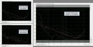
I must be missing something...
Why do you feel that the distortion curves taken with the buffered input look better?
Comparing the measurements for the "Block" transformers, the frequency response is essentially identical with or without the buffer indicating the capacitors on the sound card input were sized properly for full bandwidth audio use. Ignoring the ripples from mains interference, D4 is essentially identical as well. But, D2 & D3 are much worse with the buffer included.(D2 is 30dB worse, D3 about 10dB worse)
@ Tenson,
Did you perform a loopback test with the buffer to confirm low distortion as you did for the non-buffered setup in post#48? http://www.diyaudio.com/forums/planars-exotics/233008-esl-hybrid-5.html#post3767153
Is it possible the DC-offset of the power amp was larger when the buffered measurements were taken?
Attachments
They certainly are different aren't they.
I probably should have refrained from that statement as "they look better" before I took a closer look at the graphs.
Sorry about that, oops!!!
But there definitely is a difference between the two and this does not surprise me.
Using the Buffer will definitely isolate the sound cards impedance from the resistor divider.
I had gotten a completely different results too, although not as drastic.
I don't believe I saved any of the screen shots I did before using the buffer.
But it was when I did a loopback test with and without the resistor divider that it was not consistent between the two tests without the buffer and was with it.
I mentioned this in my earlier post.
jer
I think the results with the buffer are more accurate. It seems odd otherwise that the distortion on all three TXs was much the same. In the buffered measurements there is more difference between them and as expected the TX with higher VA rating has lower distortion in the low-mid frequencies. Additionally, the buffered tests show a more common pattern of falling level with increasing harmonic order which is not present in the other test set.
I did a 1KHz FFT test with the buffer in place and all was well, distortion around -100dB.
It just can't be accurate to drive the 10K soundcard input from a resistive divider presenting 1Meg source Z. That constitutes a pretty good current source, doesn't it?
I don't think my amp was performing any differently by the way. I even tried it from two sources - direct from my soundcard and via my Cyrus pre-amp with similar results.
As Quoted~ "But it was when I did a loopback test with and without the resistor divider that it was not consistent between the two tests without the buffer and was with it.
I mentioned this in my earlier post."
This was mainly from when I was doing Imepedance measurement curves directly into the sound card.
The FR did not change and shouldn't, I do see your point Bolserst.
I don't have all of the components at hand to get setup right away to check this on my system.
But it has got me thinking and I will dig out my apparatus and get it finished so that I can do some more testing now that I have the latest more stable version of Visual Analyzer.
There was definitely something that has added more THD compared to the earlier graphs.
All else the THD in the earlier graphs show similar consistancy's as the cores I have tested at about .05% and better.
Except the last one that shows as high as .5% THD, until 1Khz at approx. .17% and gets lower from there as the frequency goes up.
THD to dB - convert percent to decibels dB % percentage voltage % vs per cent converter THD+N total harmonic distortions calculation signal distortion factor attenuation in dB to distortion factor k in percent decibel damping - sengpielaudio Sengpiel
jer
P.S. I didn't see your confirmation while I was making this post.
Last edited:
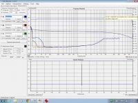
Okay! I've done a loop-back with the amp, voltage divider and buffer, but without the TX. Actually it also has my Cyrus pre-amp in line since I couldn't be bothered to change the plugs.
The voltage divider was in fact not 10meg and 1meg as I had said. It was 10meg series and 10K parallel. So this was providing a 10K output impedance on all my earlier tests.
To do the loop-back test below I reduced the series resistance to 1meg and kept the parallel leg at 10K. The amp was set to output 50V. No significant load on the amp, just the voltage divider.

I'll also say sorry that my tests are not normalised at 0dB. I don't know why they are all at around +30dB, I keeps doing it even with a feedback channel. I need to look in the settings.
Last edited:
I agree that the distortion trends for the buffered results do make more sense as far as reducing level with increased order. One other thought I had was that perhaps the results are getting contaminated with ground currents. Did you happen to run the test twice swapping the ends of the transformer secondary that your buffered probe was hooked to? This would change the phase of the distortion fed from the secondary to the probe input relative to any ground currents. If you see difference between the two measurements, the "real" answer is likely somewhere between the two.I think the results with the buffer are more accurate...the buffered tests show a more common pattern of falling level with increasing harmonic order which is not present in the other test set.
ExcellentI did a 1KHz FFT test with the buffer in place and all was well, distortion around -100dB.

At audio frequencies the 10K input impedance of the sound card will be in parallel with the 1Meg resistance, effectively shorting it. So the voltage divider for the unbuffered case is made up of 10Meg series + 10K shunt. Right? Or am I having a senior electronics moment...It just can't be accurate to drive the 10K soundcard input from a resistive divider presenting 1Meg source Z. That constitutes a pretty good current source, doesn't it?
OK. I was just asking 'cause I know some Crown amps are DC coupled and the offset does drift around a bit. I didn't know if part of the large difference in 2nd harmonic might be attributed to DC current in the primary.I don't think my amp was performing any differently by the way. I even tried it from two sources - direct from my soundcard and via my Cyrus pre-amp with similar results.
- Status
- This old topic is closed. If you want to reopen this topic, contact a moderator using the "Report Post" button.
- Home
- Loudspeakers
- Planars & Exotics
- ESL hybrid