I would have believed that a cloth would damp higher frequencies?
If so, one alternative would be to just add on backside. If it influence on higher freq, it will also influence on spread pattern, but for all we know it might improve interaction between speaker and room.
I can implement a notch filter, but in general, I believe in "making right from the start" to get the best sound quality.
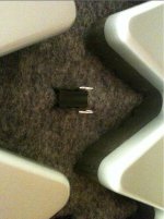
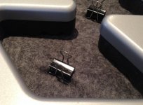
Brilliant idea regarding the paper clips. We have exactly the same type at work
Really appreciate your input guys!
In general if a cloth is thin enough it will have very little effect on treble response. However the fundamental resonance is still affected by a few db.
Too thick cloth degrades sound for some reason. Even when it's placed on the back side there is a rising of treble - likely part of the sound is reflected from the back through diaphragm.
Look at Quad esl63 how they did it .......
Just to verify; you basicly need to add some kind of air flow resistance to dampen resonance? Sounds logical when I think of it")
The resonance peak was all sorted, thanks!
I did not get the smoothing of the other dips as bolserst though:
Nicely done

Can you share details on the mesh you used and what mounting technique you decided on?
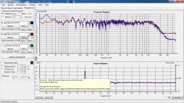
The smoothing of high order diaphragm modes is much easier to see when measuring near-field, with the microphone within 2cm of the diaphragm.
http://www.diyaudio.com/forums/plan...con-dots-resonance-control-4.html#post2010886
I used some filt. Bougt one 80% wool, 1,0 - 1,5mm thick, and one thinner 20% wool, maybe a little less than 1mm. But a quick test showed that it was actually harder to blow through the thinner filt. Thinner filt gave therefore more damping, in my case a bit too much. Though not very well tested.
I measured at a estimated 70-80cm, so I guess thats the reason why we got different results.
I measured at a estimated 70-80cm, so I guess thats the reason why we got different results.
Attachments
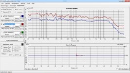
Here is a comparison between nearfield(approx an inch) vs a meter, both unsmoothed. At 1m I use relatively low SPL to reduce room effect.
Its quite obvious that you need to design system for a particular distance. Is it because of the array effect that higs get more dominant when you go further away?
Its quite obvious that you need to design system for a particular distance. Is it because of the array effect that higs get more dominant when you go further away?
Attachments
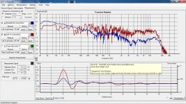
Here is a comparison between nearfield(approx an inch) vs a meter, both unsmoothed. At 1m I use relatively low SPL to reduce room effect.
Its quite obvious that you need to design system for a particular distance. Is it because of the array effect that higs get more dominant when you go further away?
Your unsmoothed near field measurement shows very effective damping of the diaphragm resonance. Congrats!
Yes, a line source will have a response trend that varies with listening distance unless it extends fully floor to ceiling in length. The reason for this is that for any given listening distance there is a frequency at which the sounds transitions from being highly directional in the vertical direction and starts to spread out. This may also be referred to as near/far field transition. The result is a -3dB/oct slope imparted to the response below the transition frequency. This is much more of a problem for full range ESLs than for hybrids, but even hybrids suffer from it if the panel is only 1m tall and listening distance is > 2m.
The formula for determining near/far field transition relative to a panel dimension is:
F = c * r / d^2
where:
c = speed of sound
r = listening distance
d = panel dimension
In general, for segmented ESLs you only need to be concerned with the transition frequency for the height.
But for wide unsegmented panels, you may see efffects of the width transistion frequency at closer distances.
If the ESL is extended fully floor to ceiling, the effective length of the line is theoretically infinite so the transition from near field to far field does not take place. Another way to visualize this is that the wave launched from the ESL would be contained between the floor and ceiling and have no way to expand or spread out in the vertical dimension.
More information here, including spreadsheet to plot transition points and response:
http://www.diyaudio.com/forums/plan...r-esl-simulator-esl_seg_ui-2.html#post2913884
Your unsmoothed near field measurement shows very effective damping of the diaphragm resonance. Congrats!
It's rather me who should send a big "thank you", for helping me resolve it.
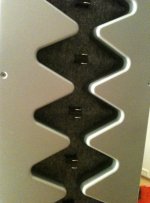
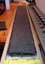
Made the modification permanent and better looking, dismounted them and placed the filt below at the full length. I think the clips are looking OK. Its at the backside anyway.
@bolserst: Are you saying that there could be significant gains by extending the height of the speaker so its all the way up to the ceiling? By more or less whatever...?
@bolserst: Are you saying that there could be significant gains by extending the height of the speaker so its all the way up to the ceiling? By more or less whatever...?
Attachments
you could as well , since the silk screen is so thing glue it on the inside of the stator. you can get all alumnium rod lose with just 2 ticks with a hammer. use spray glue on the wires ad the mesh. reglue the supports with 3 second glue. it looks the best. but you really have to know wich mesh to use because getting ris of it is not easy.
adding damping further from the menbrame will give you an uneven freq response. i think there was a test with an esl57 somehwere where they measured that. i like the clip idea for testing purpose. its the best way to go !
Oh i might be wrong about the silscreen, it depends on where the silicone dots are.
There will be gains in bass(boosting more the lower you go) if you extend the height of the ESL panel/diaphragm so it goes from floor to ceiling. This will have more benefit the further from the ESL you listen…recall how you noticed the bass falling off as you moved further from the panels. Extending just the baffle board up to the ceiling will NOT make much if any difference, it is the diaphragm area that needs to be extending. This is more of an option for those building their own panels.…Are you saying that there could be significant gains by extending the height of the speaker so its all the way up to the ceiling? By more or less whatever...?
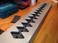
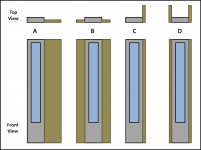
The alternative is to extend the width or depth of the side baffles, as mentioned earlier in this thread by Mj Dijkstra and etalon90 in posts #11 & #14. This will benefit the bass(boosting a uniform increment below ~300Hz, giving it a fuller sound) similarly for all listening distances. Some baffle options to experiment with are shown in the attachment. My personal preference is "A" or "B". However, if baffles are extended too far you will start getting a response notch and coloration in the midrange.
I keep meaning to ask you if your speakers are the DCM5? If so, you should have a mirror-drive transformer plus 4 step-up transformers. Next time you have the back off one of your speakers, it would be very interesting to see a picture of the transformers on the circuit board. They must be very low profile to fit inside the panel case.
Attachments
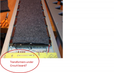
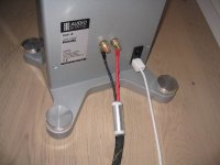
It is a low profile transformer, here are a picture. From the schematic you attached, it must be a DCM5, the RC filter in series with terminal is present, but I have bypassed it with the white jump lead you can see in the picture.
Regarding wings, I'll look into it, but the larger wings the lower fpeak, so you are loosing some of the advantages from a dipole.
Regarding wings, I'll look into it, but the larger wings the lower fpeak, so you are loosing some of the advantages from a dipole.
Attachments
Thanks for the pic!It is a low profile transformer, here are a picture. From the schematic you attached, it must be a DCM5, the RC filter in series with terminal is present, but I have bypassed it with the white jump lead you can see in the picture.
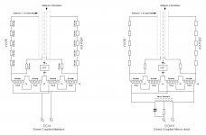
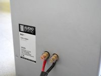
I am not sure what model you have. I only see 4 transformers, the DCM5 would have a 5th transformer for the mirror circuit. Is there a 5th transformer hidden that I can't see? Also, all of the DCM5 pics I have seen on the web show the label on the back as being DCI, but with a black marker changing the I to an M and then adding the 5. Is your label like those shown in Attachment #1, 2 ?
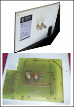
Your picture of the PCB and transformers looks essentially identical to the DCI pics I have seen Attachment #3.
However, unlike the DCI schematic shown in post#52, your ESL:
1) does not have resistors in line with central segment, and only 4 resistors in series to outer segments.
2) has R-C components in series with the transformer primaries.
You mentioned back in post#5 that R= 6.8 ohm.
Did you ever determine what value the Capacitor was?
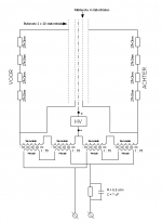
Attachment #4 is my current understanding of the circuit for your ESL.
Attachments
No, I did not look at the cap value, that would require taking it out(or maybe an dentist mirror), and its glued, so I did not take the chance. But it might be a kind of hybrid, because the dealer I bought them from mentioned that they had done a mod that was supposed to improve low end. Well, if that worked, I do not dear to think how it was before....
I'm not home at the moment, but will soon be, so I can have a check regarding label quite soon.
I'm not home at the moment, but will soon be, so I can have a check regarding label quite soon.
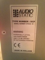
Aaaaaah...ok. I am not familiar with that model.Its a DCP.
If online research can be believed, this model originally came with 4 transformers, and no capacitor in series with the primary. Adding the capacitor may have been the modification done to it to provide a small midbass boost like the ES100 had. The boost comes from resonance between the capacitor and the transformer primary inductance. It doesn't work particularly well since the boost frequency and magnitude changes with the drive level.
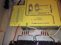
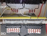
I did finally locate a picture of the DCI stator resistors.
Attached is a comparison between it and your DCP.
Note the additional resistors inline with the center segment on the DCI.
Attachments
- Status
- This old topic is closed. If you want to reopen this topic, contact a moderator using the "Report Post" button.
- Home
- Loudspeakers
- Planars & Exotics
- Audiostatic baffle step filter