Hi!
I have obsessed about ESL for some time and want to get around to fabricating my own. A headphone has been the target in my sights for quite some time. So I have some questions on the amplification methods available.
One appealing method is to direct drive it using this depiction of a Boroskie headphone tube esl amp:
http://cdn.head-fi.org/6/69/69546e18_wholecct_RV41.jpg
This is appealing to me because the necessity to match impedances are not required being that it is a OTL. Also this is nice because the PA is native to the set up.
The alternate rout is oddly Ultra simple. But I simply can't find enough literature on the subject.
Jazzman's DIY Electrostatic Loudspeaker Page: The Electronics Package
Calvin's discovery of super cheap Antek power toroids as a method of stepping up the swing is so cost effective and not time consuming that I must seriously consider it as well. This needs a PA in line... Not an issue but my fear is is matching impedances and possible capacitance problems. Being said, can anyone inform me if concerns for matching impedance is nesscesary or not with ESLs (what about at headphone levels)? I hear a lot about minimum PA wattage rating with the transformer set up. Dangers of damaging?
Tips? Bullet proof setup? Am I going to have to wait untill I fabricate my headphones before I can put metrics on what kind of driver I need?
These techniques have been discussed many many times in various threads.
If you google "DIY T2 amp" you can find projects and schematics of this beautiful direct drive amp.
Mainly at Headfi.org .
As well as the "Blue Hawaii amp" here is the schematic ,
http://gilmore.chem.northwestern.edu/bluehawaii_moda1.png
HeadAmp - Audio Electronics (Blue Hawaii SE Electrostatic Amp [BHSE])
It is similar in design to the T2, But the T2 is much much more involved but doesn't cost as much to build.
I am not sure if the original website is now defunk or not but I have found the original pages after a long hard search But I can't seem to find "headwise" at all now.
But I did find this one also designed by Kevin Gilmore that was on the Headwise website,
A Current-Domain Electrostatic Amplifier for Stax Omega II Headphones | HeadWize
Here are a few more links that might help you out for starters,
https://www.google.com/search?q=blu...lC9CWqwHGl4C4Dg&ved=0CGkQsAQ&biw=1280&bih=864
https://www.google.com/search?q=kev...ZIYm-qQH7loG4DA&ved=0CE8QsAQ&biw=1280&bih=864
Stax SS schematics?
http://img57.imageshack.us/img57/2144/hev70full9ou.jpg
The schematic to the original Stax tube amplifier can also be found using three 6xx7 double triode tubes as well as I have it some where in my archives.
here are a few designs that I had started on but never finished although I did build a 200v version,
http://www.diyaudio.com/forums/head...discrete-class-headphone-amp.html#post2596223
and a recent thread on the search for FET's
http://www.diyaudio.com/forums/planars-exotics/221050-looking-hv-fets-direct-drive.html#post3192308
http://www.diyaudio.com/forums/planars-exotics/221050-looking-hv-fets-direct-drive.html#post3240065
it was to be used with my micro driver ESL,
http://www.diyaudio.com/forums/head...ectrostatic-headphone-issues.html#post3204945
Here is a whole thread dedicated to ESL headphones,
http://www.diyaudio.com/forums/head...s-anybody-made-els-headphone.html#post1650277
And more stuff here,
My DIY Electrostatic Headphones
Driving them with transformer can be done but it is not a very efficient method.
This is because the transformers self capacitance is much much greater than that of the ESL driver itself.
Second, With the power transformer technique you won't be able to drive the primary's (6v windings) much than about 2v or maybe 4v before the onset of core saturation starts to occur at 20Hz.
However you can make them work and listenable with two cores.
I would suggest to use four core to increase the efficiency.
By the time you have all your money wrapped up in all that iron you could have built a direct drive amp suitable to drive them with a few FET's and some opamps.
http://www.diyaudio.com/forums/head...discrete-class-headphone-amp.html#post2596223
and,
Do It Yourself - Electrostatic Speakers - Project: ESL H.V. Amp by Neil S. Mckean
A detailed thread on this type of design,
http://www.diyaudio.com/forums/solid-state/170945-8-watt-hifi-few-parts.html#post2255998
I will be embarking on such an amp in the very near future after I finish my desktop ESL.
I am planning a direct drive amp for them as well as they only have a panel capacitance of 50Pf.
I have started making some headphone too,But they are not finished as well.
They are in the DIY audio thread and I used some blank (clear) cd discs to make them.
I was just undecided on what to use for a stator material but I have it figured out now.
I will be using common window screen as I had planned on in the first place.
I hope this helps you and it would be great to see your project as it gets developed.
Cheers !!!
jer")
P.S. Here is a close up cropped section of the stax solid state amp section as it shows that they are using the same ole technique!!
If you google "DIY T2 amp" you can find projects and schematics of this beautiful direct drive amp.
Mainly at Headfi.org .
As well as the "Blue Hawaii amp" here is the schematic ,
http://gilmore.chem.northwestern.edu/bluehawaii_moda1.png
HeadAmp - Audio Electronics (Blue Hawaii SE Electrostatic Amp [BHSE])
It is similar in design to the T2, But the T2 is much much more involved but doesn't cost as much to build.
I am not sure if the original website is now defunk or not but I have found the original pages after a long hard search But I can't seem to find "headwise" at all now.
But I did find this one also designed by Kevin Gilmore that was on the Headwise website,
A Current-Domain Electrostatic Amplifier for Stax Omega II Headphones | HeadWize
Here are a few more links that might help you out for starters,
https://www.google.com/search?q=blu...lC9CWqwHGl4C4Dg&ved=0CGkQsAQ&biw=1280&bih=864
https://www.google.com/search?q=kev...ZIYm-qQH7loG4DA&ved=0CE8QsAQ&biw=1280&bih=864
Stax SS schematics?
http://img57.imageshack.us/img57/2144/hev70full9ou.jpg
The schematic to the original Stax tube amplifier can also be found using three 6xx7 double triode tubes as well as I have it some where in my archives.
here are a few designs that I had started on but never finished although I did build a 200v version,
http://www.diyaudio.com/forums/head...discrete-class-headphone-amp.html#post2596223
and a recent thread on the search for FET's
http://www.diyaudio.com/forums/planars-exotics/221050-looking-hv-fets-direct-drive.html#post3192308
http://www.diyaudio.com/forums/planars-exotics/221050-looking-hv-fets-direct-drive.html#post3240065
it was to be used with my micro driver ESL,
http://www.diyaudio.com/forums/head...ectrostatic-headphone-issues.html#post3204945
Here is a whole thread dedicated to ESL headphones,
http://www.diyaudio.com/forums/head...s-anybody-made-els-headphone.html#post1650277
And more stuff here,
My DIY Electrostatic Headphones
Driving them with transformer can be done but it is not a very efficient method.
This is because the transformers self capacitance is much much greater than that of the ESL driver itself.
Second, With the power transformer technique you won't be able to drive the primary's (6v windings) much than about 2v or maybe 4v before the onset of core saturation starts to occur at 20Hz.
However you can make them work and listenable with two cores.
I would suggest to use four core to increase the efficiency.
By the time you have all your money wrapped up in all that iron you could have built a direct drive amp suitable to drive them with a few FET's and some opamps.
http://www.diyaudio.com/forums/head...discrete-class-headphone-amp.html#post2596223
and,
Do It Yourself - Electrostatic Speakers - Project: ESL H.V. Amp by Neil S. Mckean
A detailed thread on this type of design,
http://www.diyaudio.com/forums/solid-state/170945-8-watt-hifi-few-parts.html#post2255998
I will be embarking on such an amp in the very near future after I finish my desktop ESL.
I am planning a direct drive amp for them as well as they only have a panel capacitance of 50Pf.
I have started making some headphone too,But they are not finished as well.
They are in the DIY audio thread and I used some blank (clear) cd discs to make them.
I was just undecided on what to use for a stator material but I have it figured out now.
I will be using common window screen as I had planned on in the first place.
I hope this helps you and it would be great to see your project as it gets developed.
Cheers !!!
jer
P.S. Here is a close up cropped section of the stax solid state amp section as it shows that they are using the same ole technique!!
Attachments
Last edited:
Hi,
Anyway, the required current for a specified bandwidth into a given capacitance is easy to calculate.
It is common and good engineering practise to estimate and evaluate the requirements and specs first and then look for appropriate parts and devices
The same applies to the transformers. The standard power toroids may be totally fine for hybrid-ESLs, playing from >>100Hz on, but not for fullrange. They work really well with high capacitance panels, but as Jer already said, they are not as good for small capacitance panels due to internal winding capacitances and rather low transformation factors.
Jauu
Calvin
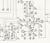
Ps. Intersting, the role of R46 in the Stax amp schematic
That is not quite correct. The cited Boroskie amp for example has quite high-valued plate resistors of 60k. This is the driving impedance for a ESL transducer that at the same forms a RC lowpass. Speaking in different terms this means that the driving current that this high impedance allows for is so low that it can't charge the ESL capacitance to full power/full bandwidth. Iirc for a typical capacitance value of an ESL headphone the drive impedance should be <30k..This is appealing to me because the necessity to match impedances are not required being that it is a OTL.
Anyway, the required current for a specified bandwidth into a given capacitance is easy to calculate.
It is common and good engineering practise to estimate and evaluate the requirements and specs first and then look for appropriate parts and devices
The same applies to the transformers. The standard power toroids may be totally fine for hybrid-ESLs, playing from >>100Hz on, but not for fullrange. They work really well with high capacitance panels, but as Jer already said, they are not as good for small capacitance panels due to internal winding capacitances and rather low transformation factors.
Jauu
Calvin
Ps. Intersting, the role of R46 in the Stax amp schematic
Last edited:
Yes, Calvin I noticed that R46.
Not quite sure what it does yet.
Maybe a current limit protection for the bottom FET.(?)
here is the data sheet on the FET,
http://www.datasheetcatalog.org/datasheet/siemens/Q67000-S284.pdf
jer
Not quite sure what it does yet.
Maybe a current limit protection for the bottom FET.(?)
here is the data sheet on the FET,
http://www.datasheetcatalog.org/datasheet/siemens/Q67000-S284.pdf
jer
Last edited:
Hi,
Yes, we know the role of R46. It makes the upper CCS a modulated CS. ;-)
The SRPP can be seen as ESL drive regularly. But since a SRPP should be optimized for a single constant impedance, it doesn´t work as intended over most of the Audo bandwidth.
jauu
Calvin
jauu
Calvin
ps. see also the DS of the Infineon 800V enhancement N-channel BSP300 and the Depletion mode types BSP129N, BSP135 and BSP149
Last edited:
Hey! Thanks so much for the links, knowledge and tips. Google searching can only take you me so far into the dark without guidance.
Logically thinking, I should make my headphone first and then construct the driving system to match. When I do fabricate my headphones, measuring the capacitance would be priority to finding how strong of a driver I need right (At higher freqs)? Is this what defines the plate resistance required for me?
At Headwize:
All-Triode Direct-Drive Amps for Electrostatic and Electret Headphones | HeadWize
What appears to be the only area for modification when using different brands of ESL phones is at Figure 5 "Biasing the headphone diaphragms" :
http://headwize.com/images/gilmore6.gif
It looks like his plate resistors per stator are set to 47k with no instructions to tweak them.
So is it really the bias that is the important value to keep an eye on right?
Again, thanks for the tips and pointers guys
Iirc for a typical capacitance value of an ESL headphone the drive impedance should be <30k.
Anyway, the required current for a specified bandwidth into a given capacitance is easy to calculate.
Logically thinking, I should make my headphone first and then construct the driving system to match. When I do fabricate my headphones, measuring the capacitance would be priority to finding how strong of a driver I need right (At higher freqs)? Is this what defines the plate resistance required for me?
At Headwize:
All-Triode Direct-Drive Amps for Electrostatic and Electret Headphones | HeadWize
What appears to be the only area for modification when using different brands of ESL phones is at Figure 5 "Biasing the headphone diaphragms" :
http://headwize.com/images/gilmore6.gif
It looks like his plate resistors per stator are set to 47k with no instructions to tweak them.
So is it really the bias that is the important value to keep an eye on right?
Again, thanks for the tips and pointers guys
Also I am curious about All tube or all SS. Being that tubes run big voltages natively, I would think it would be the proper fitting suit for the occasion. In Headwize, he has an All tube get-up AC-coupled and what looks like a hybrid that is Direct Coupled. Why DC-coupled? advantages?
Tubes cost more !!
But they do look cool.
When designing the amp you go about setting the current through the devices just as any other Class A amplifier.
Go by and use the Lowest impedance that your load will produce.
This also means by using the highest frequency that you want your bandwidth to be as well.
The higher the frequency the lower the impedance will be and thus the higher the bias current should be as it will be constant through the devices regardless of the voltage output swing.
There are limits to this statement By the output impedance and what the amp can put out.
But is just a single ended push pull Class A amplifier is all and the same rules apply.
It has been a while since I have ran the numbers.
A good spice program helps a lot with these kinds of calculations.
I use Circuitmaker 2000 and Ltspice.
I would personally would go with a 100khz bandwidth as this would allow a fairly decent reproduced square wave from 10KHZ and 20KHZ as far as slewing distortion is concerned.
Whether or not you can hear this is of another matter.
At 100Khz, 100pf= 16k (15.9k) ohms and 50pf= 32K ohms
And 50khz , 100pf= 32K ohms and 50pf=64K ohms
Also 20Khz , 100pf= 80k ohms and 50pf= 160k ohms
Just to give you an idea.
Electronics 2000 | Reactance Calculator
AC coupling is a safer method and if you use Quality capacitor's for the output the sound shouldn't be effected at all.
This way the lines won't be live when there is no signal except for the bias voltage on one of them.
In which it should have a High value current limiting resistor to be safe should any terminals get exposed.
It also eliminates any dc offset issues that may occur between the two amplifier halves as well.
Since the D/S is so small for a headphone driver these offset values could/will cause an issue on the centering of the diaphragm when there is no signal should one side of the amplifier drift off from its quiescent setting.
Output caps are an added cost as well, But either method will work well as it is a matter of preference is all.
jer
Last edited:
I think you will find the highly lauded project ESL amps, Gilmore's, and the T2 replica don't manage 100 kHz power bandwidth - the static power requirement in Class A is rather daunting
say ~ 100 pF ES headphone + cable load, 300 Vrms, 100 kHz works out to nearly 20 mApk
even with active CCS that's 18 W x 4 stator driver circuits for 72 W continuous power dissipation from +/-450 V supplies
I must say I don't understand the thinking that seems to rule out SRPP/modulated CCS for Gilmore and fan boys
my sims show the modulated CCS with depletion mode MOSFET simply presents a divided version of the Cload to beyond 1 MHz - what else do people want?
say ~ 100 pF ES headphone + cable load, 300 Vrms, 100 kHz works out to nearly 20 mApk
even with active CCS that's 18 W x 4 stator driver circuits for 72 W continuous power dissipation from +/-450 V supplies
... But since a SRPP should be optimized for a single constant impedance, it doesn´t work as intended over most of the Audio bandwidth.
I must say I don't understand the thinking that seems to rule out SRPP/modulated CCS for Gilmore and fan boys
my sims show the modulated CCS with depletion mode MOSFET simply presents a divided version of the Cload to beyond 1 MHz - what else do people want?
Last edited:
Hi,
I didn't rule out SRPP/modulated CCS at all. Its just that the working into a complex load differs from that into a real load. A line level SRPP preamp is certainly a very different application than a ESL.
Both terms describe the same functioning, which has also been named SEPP. The term PushPull indicates a symmetrical behaviour regarding the currents through the output devices.
For the classic SRPP this holds true for a specific load impedance. The impedance of a Cap varies though over the full audio bandwidth by a factor of 1000. So apart from a certain range around the optimum impedance the SRPP ceases beeing a true PP. Of course it doesn't stop working alltogether.
As far as I understand SRPP I would design it for a optimum load impedance at say 5-10kHz. This way it could provide for twice the bias current into the load, hence maximum efficiency. For higher frequencies current capability would drop, meaning a reduction of full power bandwidth. Since at high frequencies there's not much music content -and if, then with low energy content- the loss in power bandwidth would be a rather academical than musical issue.
At lower frequencies the current demand of the load sinks due to its rising impedance nature. Similarly the SRPP gradually changes towards a CCS loaded grounded Cathode/Emitter/Source circuit, with a maximum load current of once the bias.
Stability could be an issue into the highly complex load, since the modulation-sensing resistors current is also a function of the complex load current. Then the 'lower' signal generating output master device and the 'upper' CS slave may not work in synchronousity any longer.
For larger high capacitance panels SRPP/modulated CS is probabely the only acceptable drive system, sonically as well as efficiency wise
jauu
Calvin
Last edited:
I guess the issue is I really don't have much interest in tubes, especially triodes, triode strapped circuits - just use "SRPP derived" modulated current sources with SS parts that don't have mu, plate resistance, appreciable internal voltage feedback
you would proably have to cascode tubes, have a low Z buffer for screen grid with pentodes to get the sort of perfomance I see with Ixys depletion mode MOSFET modulated CS load
you would proably have to cascode tubes, have a low Z buffer for screen grid with pentodes to get the sort of perfomance I see with Ixys depletion mode MOSFET modulated CS load
Hi,
SRPP or SEPP are circuit topologies and not restricted to Tubes.
The problem of stability remains with modulated CSs, regardless of Glass or Sand.
The pros of the SRPP are high gain, lowish output impedance and high load current (twice the bias current) into the right load. This may allow for a simple circuit with acceptable efficiency and heat loss.
The cons are stability of bias points and drift due to ageing and non-symmetrical behaviour in off-optimum load impedance.
Preloading the output resistively helps the impedance problem but is no real cure. Stability and drift due ageing may be cured with a feedback loop at the cost of gain/efficiency and probabely sonics too.
A dedicated Buffer may be a solution to the drive/impedance prob. In that case a SRPP i.e. the current drive capability may not be needed any more.
I´d rather opt for a audio-signal-modulated CS cascoded by a HV-device -be it a tube or a Transistor- working into a highimpedance load, like a CCS, or a inductance. IXYS offers several veryhigh voltage/lowcurrent MOSFET devices that may be useable in a HV driver stage and HV-CCS (IXTA/IXTH/IXTV02N250, IXTF1N450, IXTF02N450, etc).
jauu
Calvin
ps. Thanks Alex for the Link to the Russian Power-JFET, a very interisting device for a highpower audio power amp. I follow these parts quite for a while, but availability and sourcing seems troublesome.
- Status
- This old topic is closed. If you want to reopen this topic, contact a moderator using the "Report Post" button.
- Home
- Loudspeakers
- Planars & Exotics
- ESL headphone driving options