Optimization of magnetic field
Hi
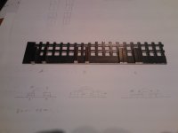
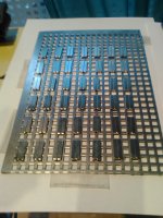
I'm trying to optimize the limited number of magnets on existence.
there are three main configurations possible, A, B and C
Anybody can tell which has the better field?
I'm pairing the magnets in order to get an workable Epsilon layout.
in any case, the gap should be 1 Cm for practical matters, mainly a decent membrane surface, about 13X16 Cm
The available magnets are 90 units per speaker.
Thanks on advance
Any advice is welcome
the magnets are these: supermagnete - Q-20-04-02-N: Bloque magnético 20*x*4*x*2*mm
Bloque magnético
Cód. artículo: Q-20-04-02-N
Material: NdFeB
Forma: Bloque
Tamaño: 20 x 4 x 2 mm
Tolerancia: +/- 0,1 mm
Peso: 1,2 g
Recubrimiento: Niquelado (Ni-Cu-Ni)
Magnetización: N45
Fza. sujec.: aprox. 1,2 kg
Temperatura máxima de empleo: 80°C
Ficha técnica en PDF
20 mm4 mm2 mm
Imanes (N45) extrafuertes.
Hi
I'm trying to optimize the limited number of magnets on existence.
there are three main configurations possible, A, B and C
Anybody can tell which has the better field?
I'm pairing the magnets in order to get an workable Epsilon layout.
in any case, the gap should be 1 Cm for practical matters, mainly a decent membrane surface, about 13X16 Cm
The available magnets are 90 units per speaker.
Thanks on advance
Any advice is welcome
the magnets are these: supermagnete - Q-20-04-02-N: Bloque magnético 20*x*4*x*2*mm
Bloque magnético
Cód. artículo: Q-20-04-02-N
Material: NdFeB
Forma: Bloque
Tamaño: 20 x 4 x 2 mm
Tolerancia: +/- 0,1 mm
Peso: 1,2 g
Recubrimiento: Niquelado (Ni-Cu-Ni)
Magnetización: N45
Fza. sujec.: aprox. 1,2 kg
Temperatura máxima de empleo: 80°C
Ficha técnica en PDF
20 mm4 mm2 mm
Imanes (N45) extrafuertes.
Hope in vain: mad:
"this time it surely go" (famous last words)
Scheme A will yield the best results.
Why not like drawing "A", but with only one magnet on each side?
Thanks for helping
The problem using one magnet is that they want to be together and you need to glue them to the base (well, on previous atempts at last). If you stack them they remain in place without glue, due to the increased down force.
However its a configuration too good and simple to be fully discarded.
Regards
Pedro
Scheme A will yield the best results.
Thanks for helping
I think I will do a comparision between A and C
The C is intended for an epsilon layout, hence the increased width of the dual magnet configuration.
Hope this not shortcircuit the magnetic field...
Thank you again
Pedro
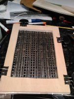
the epsilon first
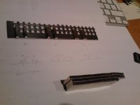
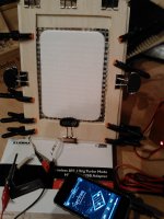
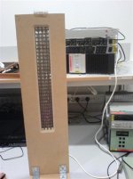
I've just put together a test rig for an epsilon layout;
a little more than 2 Ohms.
the finish i'snt Apogee standard, I know, but it's just a test bench for that tecnology
and does it works?
yes
I'll try to write details later (it's lunch time!)
"La panza es primero"
I've just put together a test rig for an epsilon layout;
a little more than 2 Ohms.
the finish i'snt Apogee standard, I know, but it's just a test bench for that tecnology
and does it works?
yes
I'll try to write details later (it's lunch time!)
"La panza es primero"
Attachments
Promising results
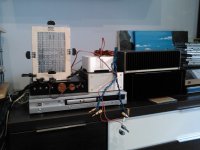
Well, how does it sound?
Not bad
The first test was taken with a 30W amp*
The sound is clear at low vol, but increase the output and the distorsion rises a lot. The aluminium foil gets as hot as the amp, struggling at less than 3 Ohm.
I though the distorsion was on the amp side, so I tried with a more powerful one, a Quad 405-2, not famous for its current capability (limited to a 8.5 A) but almost bombproof, an then, the distorsion remains.
Sure this configuration needs a lot of tweaking, so I tried the normal foil, roughly the same size, same magnets count, but the foil slighty wide, 3.5 mm to avoid heat rise. The resistance falls to 1 Ohm. Another refinement includes reducing the space magnet-membrane to a 1mm instead 3mm.
With a one Ohm resistor in series, it sound louder than the epsilon, with little less distorsion.
So I gonna tweak this one;*
- corrugate the membrane
- increase the space magnet-membrane to 2 mm with some foam to avoid premature contact at high volume and damping the foil
- diferential top-bottom stretch (anybody have tried this? I think Apogee uses it on their mid-bass panels) Don't know if it worth the effort at this size.
The latest pics later (damn ipad...)
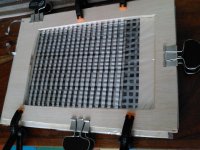
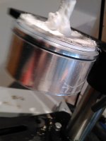
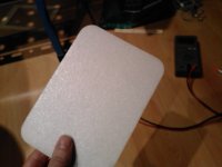
Corrugation of the membrane
I've corrugated the membrane and damped it with foam.
there have been an improvement.
the problem now is how to stretch, because of the foam.
the bass response is very limited, I'll try to know how low can go.
One question; spacing the magnets can increase the surface, but will lower the magnetic density and thus, the power output. What do you think?
Attachments
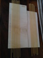
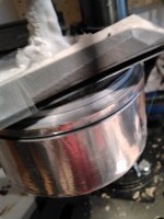
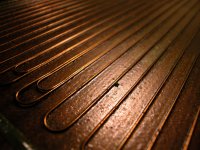
How to cut a foil and corrugate
I know everybody has its tricks, but here are some of the mines just in case they can be useful to someone.
How to cut the foil to an exact width:
I use to buy aluminium tape for chimneys and cars exhaust, then fix the roll to a vertical drill and cut it with two knifes sandwiched with something of the desired height.
The corrugation is even more simple; I use two wood plates with spaguetti glued to them; enough for the mini planars, but it is easily escalable...
Hope it will be useful to someone.
Attachments
I've corrugated the membrane and damped it with foam.
there have been an improvement.
the problem now is how to stretch, because of the foam.
the bass response is very limited, I'll try to know how low can go.
One question; spacing the magnets can increase the surface, but will lower the magnetic density and thus, the power output. What do you think?
YES SPACING THE MAGNETS WILL DECREASE THE POWER CONSIDERABLY.the magnets should cover the whole area of the cut out, and all the magnet area must be utilized. That is the whole point of using the epsilon layout. This I have found to be true from experience.
YES SPACING THE MAGNETS WILL DECREASE THE POWER CONSIDERABLY.the magnets should cover the whole area of the cut out, and all the magnet area must be utilized. That is the whole point of using the epsilon layout. This I have found to be true from experience.
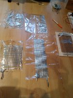
Hi Henry
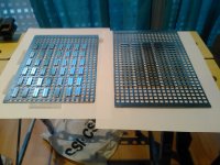
The problem with it is that the available magnets are only 2 mm wide, so the epsilon layout can't be wide enough, so I try to make it long to compensate, ending with a cuasi ribbon instead a planar.
you can compare on the pic the various membranes tested to date.
thanks for reply
Attachments
Last edited:
taming the resonances
After stretching, unstretching, corrugating and many other things that can be done to a membrane, at last one solution worked partially.
the very unpleasing resonances between 50 and 200 Hz have gone almost totally
The solution; gluing an foam plate to the membrane. Now the membrane has lost the most visible resonance modes.
The tradeoff; I think some transparency has gone, but the useable power is higher.
They can almost be used as a desktop satellites, but can't compete with the ones they must replace, so is life.
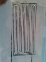
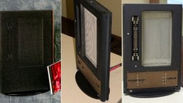
But still wanna test some ideas. One of them is try to reproduce the wire pattern seen on the real maggies. Does anybody have any sketch of that pattern?
on the pics available is difficult to follow.
Thanks on advance
After stretching, unstretching, corrugating and many other things that can be done to a membrane, at last one solution worked partially.
the very unpleasing resonances between 50 and 200 Hz have gone almost totally
The solution; gluing an foam plate to the membrane. Now the membrane has lost the most visible resonance modes.
The tradeoff; I think some transparency has gone, but the useable power is higher.
They can almost be used as a desktop satellites, but can't compete with the ones they must replace, so is life.
But still wanna test some ideas. One of them is try to reproduce the wire pattern seen on the real maggies. Does anybody have any sketch of that pattern?
on the pics available is difficult to follow.
Thanks on advance
Attachments
More data
More findings
I've testing for a while, and new data arises;
the prototype benefits of running in; now it sound better than past week.
It's relatively amplifier friendly; as I write this lines I'm using an Topping TP30, class D 15 Watts. The power is just right, 30 W would be better.
I'm using digital filters trying to discover the frequency response, and more or less it cuts somewhere between 200 and 400Hz. It's very difficult to find partly because I suspect it has a very strange response, and partly because I'm not very good playing with filters. So an eq that works fine with a track, doesn't work with another.
I've tried with the eq of the Itunes (graphic) and the parametric eq of Amarra, more powerful but more complicated.
By the way, the Amarra soft works very fine, I like it specially with the cache on.
One question; does anybody know why some of the magneplanars has doble run of wires here and there? see pic.
Thanks on advance
Attachments
Hi Karrellen
Looks like you have gotten the same idea as I about use of perforated steel plates with square holes
Couple of things:
1. Be careful of the weight of the diaphragm, as it will limit upper frequency and sensitivity. Therefor use very thin plastic ... less than 12 micrometers. Same goes for the alu foil ...
2. Skip the corrugation, and use something at the edges as dampeners (foam, rubber ...)
3. Be very careful when stretching the diaphragm (looks like you have wrinkles, and these will for sure make distortion). It also have to be quite tight not to hit the back panel a low freq.
4. A small planer like this will not play any bass ... think you need to consider a dynamic woofer for the bass .... .... this size I think is not good for under 500 Hz at best ..... unless you are playing at very low levels
Keep it up, you are on the right track for sure ...
Best regards Baldin
Attachments
Utilization of all the magnet area is very important, gaps between magnets waste the magnet area and a loss of sensitivity is one of the side effects.The weight of the diaphragm is not really important . Utilization of the magnet area is the be all and end all of the design All of my diaphragms are at least twice as heavy as they were and all are more sensitive, using the epsilon layouts, which cover width of magnets from 12.7, 18 mm and 25 mm. I will be using 6mm wide magnets and 2.5 mm wide tape when I get round to rebuilding my A4 sized planar design which wasn't very sensitive but will be vastly improved using the epsilon layouts.
Last edited:
- Status
- This old topic is closed. If you want to reopen this topic, contact a moderator using the "Report Post" button.
- Home
- Loudspeakers
- Planars & Exotics
- Mini planar magnetic using neos