The opposing magnets flatten the field lines. Does this matter and is it worth the extra cost and complexity? Several well regarded manufacturers use purely single-sided designs so that suggests things can be made to work well with a simpler system. The results with the opposing magnets look enticing, though.
Your FEMM solutions reminded me of one other reason full range single ended planar magnetic designs may tend to have the tweeter section off to the side. At low frequencies approaching diaphragm resonance modes, the IM distortion would be the highest for a tweeter section placed in the middle of the diaphragm where the membrane displacement is largest.
The Wisdom Audio driver you mentioned seems to solve this problem by using individual diaphragm sections for the central tweeter(750hz - 20kHz) and the two outer panel areas(80Hz - 750Hz).
Looking at your FEMM results again, it looks to me that multiple conductors spread in the gap would not be nearly as advantageous for single-ended magnet systems as for symmetric front-and-back arrangement used by Wisdom and BG. If I am seeing the image correctly, looks like they have 4 or 5 conductors in the tweeter gaps.They also use two-conductor alternative to Magneplanar's single-conductor per magnet gap approach.
Oh, speaking of BG, thought you might be interested in the patent for their Neo10.
Figure 3 shows 4 conductors per magnetic gap.
Patent US8031901 - Planar speaker driver - Google Patents
Interesting thought regarding intermodulation distortion. I don't yet have a sense of what the frequency of the fundamental resonance of the diaphragm will be. I know I'm not telling you anything you don't know when saying that the fundamental mode is the one that puts an antinode where the central tweeter would be and would therefore be the most problematic. I've been thinking I could keep that fundamental resonance frequency quite low and not excite it much with music because:
1) I wouldn't need to use high diaphragm tension to counteract the DC offset exhibited by biased ESL diaphragms. The low tension would mean a low resonance frequency.
2) I'll be gluing Al strips on a very thin mylar diaphragm, so the added mass should drive resonance frequency down.
3) I was hoping to cross over to a column of open baffle woofers somewhere in the 300-500 Hz range, above the range I hope to be able to force the diaphragm resonance into.
My intention to try low tension is also motivated by Capaciti's findings that a cleaner decay is obtainable by minimizing diaphragm tension and using damping material around the diaphragm edges. Your post raises the point that I should be prepared, at a minimum, to place strategically some diaphragm damping or clamping to be sure a central tweeter section doesn't get over-driven. Thanks for provoking that thought.
My view of the Wisdom system left me with the impression that there were just two conductors per gap in the woofer section. I'll definitely take another look. If your point was that multiple conductors will spread the conductors into regions where the field lines aren't oriented advantageously, I certainly agree. That's why I was going to stick with one or two conductors that I could fit into the "hot spot" of the magnetic field. If I've misunderstand your intention, please let me know.
Few
Interesting thought regarding intermodulation distortion. I don't yet have a sense of what the frequency of the fundamental resonance of the diaphragm will be. I know I'm not telling you anything you don't know when saying that the fundamental mode is the one that puts an antinode where the central tweeter would be and would therefore be the most problematic. I've been thinking I could keep that fundamental resonance frequency quite low and not excite it much with music
Yeah, this would certainly be more of a problem for a full range design than a hybrid like you have in mind where you design for resonance placed well below crossover. But, I'm sure you know that the dipole woofers placed beside the ribbon will have no problem exciting the resonance through acoustic coupling. I think your thought that some strategically placed damping may be in order is a good one. Note that all sections of the Wisdom drivers had some damping applied to them.
Looked to be 2 conductors per gap in the woofer sections, 4 or 5 per gap in the tweeter.My view of the Wisdom system left me with the impression that there were just two conductors per gap in the woofer section. I'll definitely take another look.
Yes, that's what I was getting at.If your point was that multiple conductors will spread the conductors into regions where the field lines aren't oriented advantageously, I certainly agree.
Good point about the acoustically driven resonance. Dang. I guess I'll have to orient the woofers perpendicular to the planar magnetic diaphragm (and aim their dipole node at the listener) I guess damping/clamping will be the plan.
My SketchUp diagram shows a different spacing of conductors than what I'd likely aim for. I was being lazy when drawing. I was actually thinking I would have a small gap between the two conductors in the same gap, and a larger gap between conductors over the magnets where the force wouldn't be in the right direction. I still need to play with the constraints of impedance, BL product, radiating area, magnet cost, expansion of the universe...man what a way to make a living.
Thanks for catching the flaw in my reasoning.
Few
I guess damping/clamping will be the plan.My SketchUp diagram shows a different spacing of conductors than what I'd likely aim for. I was being lazy when drawing. I was actually thinking I would have a small gap between the two conductors in the same gap, and a larger gap between conductors over the magnets where the force wouldn't be in the right direction. I still need to play with the constraints of impedance, BL product, radiating area, magnet cost, expansion of the universe...man what a way to make a living.
Thanks for catching the flaw in my reasoning.
Few
Interesting thought regarding intermodulation distortion. I don't yet have a sense of what the frequency of the fundamental resonance of the diaphragm will be. I know I'm not telling you anything you don't know when saying that the fundamental mode is the one that puts an antinode where the central tweeter would be and would therefore be the most problematic. I've been thinking I could keep that fundamental resonance frequency quite low and not excite it much with music because:
1) I wouldn't need to use high diaphragm tension to counteract the DC offset exhibited by biased ESL diaphragms. The low tension would mean a low resonance frequency.
2) I'll be gluing Al strips on a very thin mylar diaphragm, so the added mass should drive resonance frequency down.
3) I was hoping to cross over to a column of open baffle woofers somewhere in the 300-500 Hz range, above the range I hope to be able to force the diaphragm resonance into.
My intention to try low tension is also motivated by Capaciti's findings that a cleaner decay is obtainable by minimizing diaphragm tension and using damping material around the diaphragm edges. Your post raises the point that I should be prepared, at a minimum, to place strategically some diaphragm damping or clamping to be sure a central tweeter section doesn't get over-driven. Thanks for provoking that thought.
My view of the Wisdom system left me with the impression that there were just two conductors per gap in the woofer section. I'll definitely take another look. If your point was that multiple conductors will spread the conductors into regions where the field lines aren't oriented advantageously, I certainly agree. That's why I was going to stick with one or two conductors that I could fit into the "hot spot" of the magnetic field. If I've misunderstand your intention, please let me know.
Few
I think that it is only (or at least mainly) that there could be more excursion in the center than at the edges, which would modulate a tweeter more than if it were placed near an edge. I am also thinking that, maybe, looking at it like it's a classic "elastic membrane vibration" situation, with nodes and anti-nodes, etc, "should" not be too relevant to this application.
The foil strips will not be vibrating like strings would, with waves superimposed on them, such that a wave equation or something predicted by the calculus of variations should be used to best-describe their motion. Nor will the membrane (except maybe a little, but only in the most-basic "single" mode, I think). No, I think that this is (or should be) a fundamentally different type of system, for the most part, and for your purposes, mostly (except maybe for basic resonance-type problems).
Think about how the membrane is driven: It is not the classical single-point forcing function (or initial displacement) of vibrating elastic membrane theory. Essentially, the electric current is the same, everywhere, at any instant (at least in terms of audio frequencies). Therefore, the entire membrane (more or less) will be forced to move forward and backward, all at the same time, except that the edges are constrained.
In some ways, this has much more similarity to a vibrating truly-rigid plate than it does to a vibrating elastic membrane. In fact, if strong-enough forces were induced on the current by the magnetic field, and the edges were not constrained, then it would be almost identical to a vibrating completely-rigid plate, because the membrane basically could not bend at all and would always stay perfectly flat/planar, if all points on it were controlled with exactly the same magnitude of force and thus had the same displacement, at all times.
So, for the most part, we would want to hope (if the magnetic field were strong-enough) that all points on the membrane would move in unison, with identical displacements, except near the edges. But, of course, because the edges are constrained and the membrane is slightly elastic, the displacement might continue to increase as we look farther from the edges. But we should hope and would like to be able to expect that there will be no other wave-like structures in the displacement itself, e.g. at any harmonics of the driving signal's frequency components, and that the elastic effect wouldn't become a dominant characteristic.
It might be nice if we could use a non-elastic membrane with an elastic area only near the edges, or, ideally, maybe, an unconstrained non-elastic membrane, driven all the way to the edges. (I suppose that with a typical real membrane there might also be some good way to lower the driving forces closer to the center, to make the membrane stay more planar.)
I'm just making this up as I go and everything I've said could be wrong. And even if not, reality probably includes some combination of "rigid" controlled planar motion and classical elastic membrane motion, for planar magnetic types of speakers.
At any rate, except for lower cost or greater simplicity, I can't see any reason that the tweeter should be on the same membrane as anything else, at least not without some mechanical isolation mechanism. It would just be one more way to get distortion. And for anyone trying to make a full-range planar setup, it would also be a limiting factor for low-frequency amplitude, as it is with my Magnepan MG-12/QR speakers, now that I have enough power to drive them to extremely-loud levels without amplifier clipping (400 W/ch @ 4 Ohms): The bass begins to significantly distort the tweeter before anything else as bad happens.
Cheers,
Tom
Last edited:
Good point about the acoustically driven resonance. Dang. I guess I'll have to orient the woofers perpendicular to the planar magnetic diaphragm (and aim their dipole node at the listener)
I didn't mean to imply the situation was unworkable, just that you needed to keep it in mind.
You might check out how Martin Logan dealt with this issue in their Statement 2 hybrid ESL.
Adding an air gap between your planar baffle and your dipole woofer column will help.
Adding a rearward projecting baffle board on the inner edge of the woofer column will as well.
Think about how the membrane is driven: It is not the classical single-point forcing function (or initial displacement) of vibrating elastic membrane theory. Essentially, the electric current is the same, everywhere, at any instant (at least in terms of audio frequencies). Therefore, the entire membrane (more or less) will be forced to move forward and backward, all at the same time, except that the edges are constrained.
Hello gootee,
It seems no matter how uniformly an edge clamped membrane is driven, it still tends to do what membranes like to do when excited with transients...form nodal patterns. The lower order odd modes which tend to be dominate, have the center part of the membrane moving considerably further then the edge.
I have measured them on ESLs:
http://www.diyaudio.com/forums/planars-exotics/168069-esls-have-bad-decay-plots-2.html#post2209896
They were also easy to see with a strobe light when driving a planar like the MMG.
I didn't mean to imply the situation was unworkable, just that you needed to keep it in mind.
That's how I took it; the melodramatic response was all in fun. There will be at least some air gap between the woofers and planar magnetic so I'll first determine whether there's a problem and if there is I'll seek ways to cut down the pressure gradient or clamp the diaphragm, or some combination.
Thanks for providing the link to your ESL mode experience. I was going to try to dig that out as evidence that the drum head modes really do matter but I'm glad you beat me to it. It's too bad resonant systems are so easy to make resonate!
Few
At any rate, except for lower cost or greater simplicity, I can't see any reason that the tweeter should be on the same membrane as anything else, at least not without some mechanical isolation mechanism.
For me lower cost and greater simplicity are significant drivers of the design. I also want to maximize the symmetry of the system, especially those parts that radiate short wavelength sound, so that it behaves as much as possible like a single full-range unit.
The central tweeter that was the point of this thread is intended to achieve a cylindrical wave front analogous to the spherical wave fronts generated by speakers from Thiel, Quad, KEF, and quite a few others. There seems to be growing consensus that off-axis response is more important than previously appreciated (likely to be true especially in my VERY live listening room) so I want to ensure the on-axis and reflected off-axis sounds are as similar as possible. If the tweeter is off to the side instead of centered it'll be harder to ensure the reflections mimic the on-axis sound.
Few
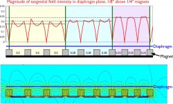
In order to make it easier to compare the magnetic field's strength, orientation, and homogeneity for different magnet spacings I drew up a FEMM model with three different spacings. I'm still using NdFeB magnets that have 1/4" x 1/4" cross sections. The attached figure shows magnet spacings of 1/2", 3/8", and 1/4" (reading from the left to the right side of the diagrams).
I also calculated the absolute value of the component of the field strength that actually moves the diaphragm---the component of the field that lies parallel to the diaphragm. I assumed the diaphragm and conductors would be 1/8" above the faces of the magnets. The upper graph shows the result.
It's interesting to see the saddles in the graph for the 1/2" spacing case (left end of the diagram). That means that near the edges of the magnets the field lines aren't oriented in the right direction, but they're so closely spaced that the desirable component of the field is still largest there.
For the sake of argument, let's assume 1/4" wide conductors. My take on the upper diagram is that you're better off fitting two runs of those conductors above magnets spaced by 1/2" rather than a single run over the 1/4" gap. The field strength in the 1/2" case is more than half of what it is in the 1/4" case, and by doubling the conductor length you get double the force. There's also a larger radiating area. All this adds up to higher sensitivity and more acoustically open area behind the diaphragm. Can anyone confirm or shoot down this reasoning? I realize some method for ending up with the same impedance in both cases will be necessary in order for this simple analysis to apply. I'm also working with a fixed number of magnets, in order to compare approaches with similar cost.
I hope the graphs make some sense...
Few
Attachments
Two conductors, each with half the current?
I would try going down to 2 mm, or whatever it takes to get the field to be parallel to the membrane, everyplace there will be any part of a conductor. Otherwise, the force on the current will not be perpendicular to the membrane.
Is there some way to set the resolution, in FEMM? It seems like the results should be more uniform. So maybe we're not getting a true picture.
What are the units of the field strength, in your plot? I have a DC Gaussmeter with a very small directional probe, and will go try to measure what the field strength is at a few points on my Magnepan MG-12 speakers, just as a frame of reference. Will report back.
OK. I put the probe's sensor tip against the mylar membrane, so it was measuring the maximum reading, which looked like it occurred when it was seeing the field that was parallel to the membrane. I measured both the tweeter section and the mid/bass section. I measured both when just barely at the membrane and also when pushing the membrane until it was bottomed-out against the magnets. For the tweeter section, I measured below the foil, where there was no foil but there were still magnets. Then I measured in the center of one of the strips of aluminum foil and the measurement was the same. For the mid/bass section, I had to place the probe tip against the side of one of the aluminum wires.
With a thin piece (about 0.5 mm) of very-slightly magnetized steel, I tested the probe of the HangZhou BST-200 Teslameter (Digital Gaussmeter). I used the probe with its protective cover removed, so I could use the tip and orient it as needed. The tip is a piece of what looks like PCB material, about 1 mm thick and 3 mm wide, and protrudes about 40 mm from the probe body. At the tip of the protrusion, there is a Hall-effect sensor. I used the edge of the slightly-magnetized thin steel sheet to see where on the probe tip the measurement was occuring, and the peak is in the first millimeter of it, although the first two millimeters respond much more than farther down the protrusion. The first 2 mm are black and look like the actual measauring component. It may be that the measurements below are the average for 1mm back from the actual tip of the probe. I have no way to know. The manufacturer's website is http://www.hzmagnet.com, according to the label on the back of the unit, which I purchased new on ebay.
When measuring at the surface of the mylar, if I carefully turned the probe tip 90 degrees, the reading went to zero. So it looks like it is nicely directional. Going another 90 degrees got to the same reading as before, except with the opposite sign. I used what is labeled as the "200 mT" scale, on the meter, which should have a resolution of 0.1 mT, according to the manual. So I just assumed that the units were mT. I could be wrong. 1 mT = 10 Gs, according to the manual.
Magnepan MG-12/QR speaker, magnetic field measurements:
TWEETER:
Membrane at rest: 35 mT
Membrane pushed in, touching magnets: 70 mT
Membrane distance from magnets: about 1 mm
MID/BASS:
Membrane at rest: 30 mT
Membrane pushed in, touching magnets: 80 mT
Membrane distance from magnets: about 3 mm
Last edited:
Thanks for the real world magnetic field measurements. Very helpful. The units in the graph I posted are Tesla so it looks like the field in the system I modeled would be quite a bit higher than that in the Magneplanars--maybe by a factor of 6 to 8. If I were to reduce the diaphragm-to-magnet distance a bit that factor might ease a bit higher but I don't yet know how much diaphragm displacement I'll need.
The point I was trying to make regarding the tangential field strength is that even if the field lines run in some direction other than parallel to the diaphragm they can still contribute usefully to the desired diaphragm motion. If they have a significant component that is parallel to the diaphragm, that component counts.
I understand that your concern is that forces in the wrong direction could cause diaphragm deformation rather than semi-pistonic motion. I see conflicting evidence in that regard. I don't doubt the validity of the underlying argument, the question is how things play out in practice. The ongoing discussion in the Analysis Epsilon thread seems to suggest conductors located in less-than-textbook positions are advantageous. I wouldn't want to put a conductor directly over the face of a magnet where the field lines run entirely in the wrong direction, but I'm beginning to think they need not be confined to regions where the field lines run precisely parallel to the diaphragm.
I also want to point out that even if the conductors are confined to the ideally oriented part of the field, the parts of the diaphragm that have no conductor are not going to be driven. The result will be alternating regions of driven and undriven diaphragm which could lead to the same rippling or puckering type of diaphragm deformation described above.
If anyone can point to some measurements that help shed light on this question I'd be very interested.
Thanks for providing the link to your ESL mode experience. I was going to try to dig that out as evidence that the drum head modes really do matter but I'm glad you beat me to it. It's too bad resonant systems are so easy to make resonate!
Hello Few,
Not sure if you had seen the attached patent, but thought you might find it useful or at least interesting.
Basically, the patent is for the technique of damping membrane modes in a planar ribbon by strategic variation in the % open area of the plates holding the magnets.
Looks like you need to use pretty low % open area to provide adequate damping though, so maybe not particularly useful for mid/tweeters.
Attachments
Thanks for the patent link. Reminds me of your exploration of ESL diaphragm damping. The table showing higher SPLs from the same maximum displacement after damping the modes is particularly interesting.
I agree that the price paid in the high frequencies in order to damp the low frequency modes may be too high. One of the reasons I'm hoping to get satisfactory performance from a single-ended design rather than a symmetric one using two parallel arrays of magnets is I like the idea of minimizing the obstructions between the diaphragm and the listener. I'm not sure if you come out ahead with this approach but I guess I'll find out. At least the cost of the magnets is considerably less!
Some old Infinity EMIT planar magnetic tweeter literature shows much improved cumulative spectral decay (CSD) behavior after adding some fibrous damping between the diaphragm and the magnets, or between the diaphragm and the plate supporting the magnets--can't remember which.
----
Actually, while trying to track down the diagram I was remembering, I ran across this, which describes Infinity's use of laminated diaphragms to control their break-up. I don't think I remembered that feature of their design; maybe others are already well aware of it. They ended up with quite thick diaphragms but report clean CSD results.
Few
Hi gootee,
I'm having trouble with the hzmagnet link and my searches aren't bringing anything up for the company. I didn't find anything after a quick ebay search either. Do you have any other info that might help put me on the right trail?
Thanks.
Few
This looks like the correct website:
Wholesale BST200 Gaussmeter - Hangzhou BST Magnet Co.,Ltd.
And here are a lot more:
http://www.google.com/#hl=en&cp=29&....,cf.osb&fp=4a14d12abcee4056&biw=1280&bih=808
This ebay one (below) looks fairly close. Not the same but looks like the same probe. The black part with the rounded end can be unscrewed and removed, to expose the small flat probe.
DC/STATIC MAGNETIC FIELD/TESLA/GAUSS METER/TESTER,AC | eBay
Also, do a search for gaussmeter on ebay. Just watch out for all of the ones that don't go down to DC!
Last edited:
How would we determine the optimum gap between the mylar and the magnets, for given magnets and given the range of amplifiers that might ever be used?
There are equations for the force on the conductors:
Magnetic Force on a Current-Carrying Wire
Magnetic field - Wikipedia, the free encyclopedia
And there are equations for the static and dynamic position and motion of the diaphragm (won't go into that here).
And there are also constraints (or at least one constraint):
If we had a testbed in which the diaphragm-magnet gap was adjustable, we could apply the expected "max upper limit" DC current in the direction that pulled the diaphragm toward the magnets and adjust the gap so the two weren't touching.
We could use an adjustable DC current source to determine the max upper current limit for a particular gap size.
We could use an adjustable DC current to easily measure the basic static linearity of the membrane displacement versus the current. AC tones could be could be used to get measurements of dynamic linearity of displacement versus amplitude at various frequencies. Software like Arta and a measurement microphone could help us understand the sensitivity of distortion versus the non-linearity.
Maybe ideally the gap should even be adjustable, depending on average signal amplitude, to get the most-accurate sound reproduction at lower volumes but also allow for much larger displacements for high volume settings.
Just thinking out loud.
Last edited:
Thanks very much for the links. I just found a source of Hall effect sensors (Allegro) willing to send up to 25 samples so I've emailed the local distributor. It looks like you apply 5 VDC and ground to two pins and measure the voltage on the third. Even I can handle that. The problem will be zeroing the DC offset (they provide a rough calibration curve in mV/gauss). I may start with that approach if the free samples come through. I'll definitely check out the links, though.
I fear that DC current-based measurements may lead us astray, depending on what we think we'll learn from them. Resonances within the driver's bandwidth (or even outside that bandwidth if driven acoustically, as Bolserst pointed out) are likely to lead to larger displacements than the rest of the frequency range and DC measurements won't reflect that effect. I think AC signals will be necessary to measure displacement limitations. I do agree an adjustable diaphragm-to-magnet distance would be handy. I hope to build a system with interchangeable spacers for that reason.
Thanks again for the links.
Few
- Status
- This old topic is closed. If you want to reopen this topic, contact a moderator using the "Report Post" button.
- Home
- Loudspeakers
- Planars & Exotics
- Planar magnetic with central tweeter?