Hi,
I get the impression, that somehow in one of the setups had been a mistake. I don´t know of any other reasonable explanation that backs up Tyus claims.
There´s hardly anthing as undisputable as the need for bias in an ESL.
The only chance to omit with an dedicated Bias supply would be the use of an electret material. All other configurations need a bias supply, which of course has to be connected to the diaphragm and the stators via means of conducting elements.
Tyu why do You insist on using slang instead of plain understandable english? As a native speaker this could be regarded as unfriendly behaviour against those forum members who don´t talk english as native tongue. How´d You like If I´d talk german to You, or other guys talk dutch, chinese, french or whatever to You? It´s for good reason, that the forum rules ask for plain english, or an translation. Sorry for OT, but I´m out of this.
jauu
Calvin
Since (C) will not charge the diaphragm, the only logical conclusion is that you are using configuration (D). I know you said the circuit board just has a loop on it, but you might check more carefully, on both sides. Look for traces hidden under the terminal block. Or, forget about trying to trace the circuit and just measure with an ohm meter. I'm sure you will find conductivity between the terminal block where you connect the stator and the secondary of the HV transformer on the circuit board as shown in the schematic.(C) This is the configuration tyu posted at the beginning of this thread. The HV supply connected to nothing but the diaphragm. Theory and experiments agree that the HV supply will not charge the diaphragm unless it is connected to both the diaphragm and stators.
You say this...but it playing here now an has been for years just like you show in C...go figg...
I do find it funny that any one would put the neg. input of a amp on the 0of a bias when if like most setup well work with just the 0of the bias on the windings to charg the panel...in your theory?...this can not sound good...an would not bias 0 have the ac v there the bias is floting....no earth....an no amp neg amp input..if you were going to put the bias 0 in...that would be a nef right
You are correct, there is no reason to need an earth reference on the secondary side of the step-up transformer for the ESL to work properly. I would bet that most DIY ESLs are constructed this way.
Last edited:
Agreed. ESLs may sound magical, but the electrical principles by which they operate are not.There´s hardly anthing as undisputable as the need for bias in an ESL.
The only chance to omit with an dedicated Bias supply would be the use of an electret material. All other configurations need a bias supply, which of course has to be connected to the diaphragm and the stators via means of conducting elements.
Thanks for all your time an under standing....
An i have had Soundlab A3...an a lot of Acoustats...an the logans....only the logan an this was in the 90 had the setup with no o in the mix...An i think it was a fluk...I think thay mint to put the 0 in the mix just like you guys have said...you are right.
I am the one who then set out to get my head around this...So i went to the other ESL that were at hand...an pulled the earth...an then get 0 off the bias out of the tranfourmer setup...I like the sound
So i just lived with it for 5-6 years with no down side.. i could see...i would take a pr of speakers an just do one speaker at a time...an get others to help me ..i did not trust myself...an evey time thay found the speaker with the bias out of the mix to sound better..So i move on to the newer ML an set them up this way an so far all are happy.
All the new logans have the 0 in...an the earth has been out of all the logans i have had
My hands on... Now were here..
Thanks
Hi,
I was reading this tread and got some thinking...
I would say it is a fact that a higher bias voltage will lower resonance frequency
So how would the resonance frequense react if the stators getting also a bias voltage!?
Special if the stators getting the opposite biasing then the d/s must be increased also it should negativ influence THD in the low end but increase the sound pressure similar a low ohm film
Just thoughts wat you think about??
Is it possible to bias the film and stator positiv to equal not constand d/s
the idear if film and stator biasing positiv the film will resive a forse the be exactly in the center
If possible how would the resonance frequense react?
Best regards Paul
The SPL output of an ESL is proportional to the charge, Q, stored on the diaphragm.…So how would the resonance frequency react if the stators getting also a bias voltage!? Special if the stators getting the opposite biasing then the d/s must be increased …
The resonance frequency decreases with increasing Q.
Q = C x V (where C = stator to diaphragm capacitance, V= stator to diaphragm DC voltage)
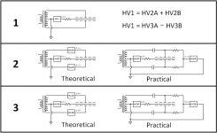
In the attached picture, Configuration 1 is the standard ESL arrangement.
Configuration 2 is the arrangement you are suggesting. If you trace out the circuit you will see that adding HV2B to the stators with the opposite polarity will increase V. In fact, you can get the same result by increasing HV1 in Configuration 1 such that it equals the sum (HV2A + HV2B). The SPL and resonance frequency will change appropriately.( ie SPL increases, Fs decreases)
Configuration 3 shows this arrangement, and tracing out the circuit you will find that adding HV3B to the stators with the same polarity as HV3A will decrease V. Similarly to Configuration 2, you can get the same result by decreasing HV1 in Configuration 1 such that it equals (HV3A - HV3B).Is it possible to bias the film and stator positive to equal not constand d/s
the idea is if film and stator biasing positive the film will receive a force the be exactly in the center
If possible how would the resonance frequency react?
If you set HV3B = HV3A little or no charge will collect on the diaphragm so there will be little or no audio output, just like if you set HV1 = 0.
Attachments
Hi,
elektrical i fully agree
but mechanical im not sure
lets simulate the stator filme distance is once 1mm and once 2mm without any voltage supply
if some voltage (+4000V) connected to the film then the closer stator will act like a stronger minus so the film should move to the closer Stator till the Forces are equal = the D/S gets more unequal
if some voltage (+4000V) connected to the film and some voltage (~+10v) to the Stators then the film should move to the more away Stator till the Forces are equal = the D/S should come more equal
??
Regards Paul
Last edited:
- Status
- This old topic is closed. If you want to reopen this topic, contact a moderator using the "Report Post" button.
- Home
- Loudspeakers
- Planars & Exotics
- Geting better output of the ESL panel