The crossover is located in the woofer box...somewhere. The SPW was assembled at Rockford's Carbonneau speaker-manufacturing facility so I never actually looked inside one.
The woofers were custom designed and manufactured at Carbonneau for the SPW, and no, I don't have any spec's on it. Since you have two SPW's, and they're really designed for stereo-use, perhaps you could use one for parts to get one in good working order.
Thanks Andy, that's the plan. I will probably rebuild both of them and sell one off. Make someone else with Acoustat Spectra's happy! I think they call that "Audiokarma"!
")
Andy what would happen if the blue speaker wire was connected to the red post and vise versa on red wire to blue post on interface.
The speaker would probably play, sort of, as it would still have some attraction/repulsion forces going on. At the very least it would sound horrible.
I can also envision some possible damage to the panel, as the red bias wire is meant to be fed from a very high impedance source, which the blue terminal is not. If this incorrect connection was made only for a short time, and at low levels, you may be okay. The symptoms of a damaged panel would probably be rather obvious, like not working at all.
It is for this reason that Acoustat color-codes the panel wires, and in the case of pre-Spectra models, even uses different connectors on the diaphragm and stator wires.
Hi im new here,
I had a problem with my speakers also and i wanted to share my experience with you guys.
My right speaker volume started to sound low .
after encountered this thread i ordered Vishy's GP02-40 Diodes from Aliexpress.
5pcs for 3$. ordered 10pcs.
Send free 5PCS GP02 40 GP02 40 E3 DO15 New original spot selling integrated circuits The second triode -in Integrated Circuits from Electronic Components & Supplies on Aliexpress.com | Alibaba Group
Diode PDF:
http://www.vishay.com/docs/88635/gp0220.pdf
After replacing them the speaker volume is fine again.
Thank you guys for the great info.
I have a slight (?) mismatch in bias voltage between two interfaces. Apologies to all if this has already been answered, but I wasn't able to find an answer with Google or by searching this thread.
I'm working on a pair of MK121-C interfaces and have just replaced the high voltage ladder capacitors. Using a Fluke 1000:1 high voltage probe, the voltage readings are 4.95 volts at the 5k site and 3.32 volts after the resistor (at the red connection) in one interface, but in the other interface, they're slightly lower - 4.80 V and 3.15 V. The line voltage transformers seem fine - putting out just under 800 VAC for both interfaces at the base of the ladders. My question is - "Are these bias voltages close enough"? What is the "acceptable" range of voltage mismatch between two interfaces? If a 150 volt difference is not acceptable, then should I replace the diodes with the Vishay GP02-40s?
Thanks in advance for your guidance!
Where your measurements taken with or without the panels hooked up to the interfaces?
If they were hooked up, this might indicated one of your panels has some leakage.
Try measuring without panels hooked up.
If measurements were taken without panels hooked up, personally I would replace the diodes.
If interested, you could measure across each capacitor and compare between the two interfaces to determine which diodes are giving the loss.
You should get about 1kV across the first capacitor in the ladder, and 2kV across each of the others.
Thanks for responding.
The measurements were taken without the panels hooked up.
If I walk the probe up the ladders for each interface, I get the following voltages:
Interface A B 1.11 1.10 2.20 2.17 3.24 3.16 4.17 4.05 4.96 4.80
I don't see an obvious glitch in these readings.
I pre-measured the caps and tried to assign them evenly between the two interfaces if that matters.
Still wondering whether these differences are "normal" or not...
I have a slight (?) mismatch in bias voltage between two interfaces. Apologies to all if this has already been answered, but I wasn't able to find an answer with Google or by searching this thread.
I'm working on a pair of MK121-C interfaces and have just replaced the high voltage ladder capacitors. Using a Fluke 1000:1 high voltage probe, the voltage readings are 4.95 volts at the 5k site and 3.32 volts after the resistor (at the red connection) in one interface, but in the other interface, they're slightly lower - 4.80 V and 3.15 V. The line voltage transformers seem fine - putting out just under 800 VAC for both interfaces at the base of the ladders. My question is - "Are these bias voltages close enough"? What is the "acceptable" range of voltage mismatch between two interfaces? If a 150 volt difference is not acceptable, then should I replace the diodes with the Vishay GP02-40s?
Thanks in advance for your guidance!
There will be some inevitable variation between speakers due to tolerances of transformer windings, diode conductance and capacitor value. The voltages you measured are within the expected range of "acceptable" values. Replacing the diodes may help, due to the age of the original diodes, but that's not a guarantee.
It is only in the Spectra series of Acoustat speakers, with the ultrasonic bias supply, where the bias voltage can be adjusted for an exact match between speakers.
What causes bass distortion when humidity rises suddenly after heavy rainfall? Is it a bias thing or diaphragm related? Is it possible to fix?
When you say 'bass distortion' I assume you mean a tendency to crackle or make static-like noises on large bass excursions. Yes, this is both a bias and diaphragm related issue.
All full-range electrostatic speakers will exhibit this behavior at some point of bass excursion. And the smaller the diaphragm area, the easier it is to reach this limit. Under conditions of high humidity, the point at which the speaker will do this becomes lower in level. However, you may have an accumulation of dust or debris caught in the gap between diaphragm and stator wires that is lowering the level at which this occurs. The dust compromises the insulating qualities of the air in the gap, and when subjected to humidity, the dust becomes even more conductive. This causes small, localized discharges of the bias voltage, and hence the snap-crackle-n-pop. For the Acoustat design, this cases no damage, but not necessarily true of other brands of ESL.
I suggest you completely discharge the speaker, remove the grill cloth, and vacuum both sides of the panel. Better yet, gently use compressed air to blow out the speaker. This is a lot of work (especially removal and reinstallation of the grille cloth) so if the issue is not causing you a lot of grief, then just skip it and don't play your system as loud when the humidity is high.
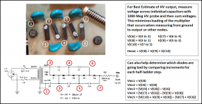
To minimize loading on the multiplier, it is best to measure the voltages across each individual capacitor rather than walk up the ladder measuring relative to ground. Summing up voltages measured across the individual capacitors will give you a much better estimate of the true output voltage of the multiplier.The measurements were taken without the panels hooked up.
If I walk the probe up the ladders for each interface…
As AcoustatAM mentioned, there will be the inevitable variations in component values resulting in mismatches in HV output. However in your case, you confirmed that the AC voltage magnitude feeding the multiplier was the same for each supply. Also, you evenly distributed capacitor values when replacing. So, any difference in output would be caused by the diodes. Your HV output difference is 3% which would cause a sensitivity mismatch of about 0.3dB. Not likely to be noticeable as a shift in acoustic image towards the louder channel.I pre-measured the caps and tried to assign them evenly between the two interfaces if that matters. Still wondering whether these differences are "normal" or not.
For reference:
1) HV output difference is directly proportional to AC voltage input. So if input voltage is mismatched by 2%, you would expect output voltage to be mismatched by 2%.
2) If you had one supply with all caps 10% above nominal value and the other supply with all caps 10% below nominal value, the difference in HV output would be about 50Vdc.
Attachments
Mr Answerman, here's a curly one for you.
My 2+2 play beautifully for a for days, and then the the efficiency of one panel drops as though the power cord has been pulled.
Turn everything off and give it 24 hours and it comes back to life again, playing perfectly again, for anything from 12 to 36 hours till it shuts down again.
I replaced the hv diodes and caps, same result, could it be the 500M resistor?
What is the wattage of this resistor?
Mr Answerman, here's a curly one for you.
My 2+2 play beautifully for a for days, and then the the efficiency of one panel drops as though the power cord has been pulled.
Turn everything off and give it 24 hours and it comes back to life again, playing perfectly again, for anything from 12 to 36 hours till it shuts down again.
I replaced the hv diodes and caps, same result, could it be the 500M resistor?
What is the wattage of this resistor?
It is highly unlikely that the 500-Mohm resistor is the culprit here. But for FYI, it's wattage rating is really irrelevant: the voltage rating is what is important, which should be a minimum of 5000 volts.
I suspect you have some foreign material caught in the gap between the diaphragm and stators which is causing an intermittent discharge of the bias. I recommend a thorough vacuuming and/or blowing out with compressed air. The procedure has been discussed in previous posts within this thread.
Update, I cleaned panels with vacuum and air. Still the same problem, good for two-three days then loss of volume in left panels.
I changed interface from left to right and that confirmed problem is in interface.
So I have an intermittent problem after a few days of running.
I've replaced diodes and caps, and got good measurement, it must be another passive component going out after a few days.
Any idea what components can fail long term, the megohm resistor, the transformers?
Hmmm, no answers, does that mean I have an unique problem never seen before!
Tried something different, I cleaned the HV boards with spray on cleaner, and put it back in system, it now is louder than the "good" side, had to adjust balance control to equalise volumes. I guess that shows how vulnerable the stats are to leakage, hopefully the charge will maintain for more than a few days.
Tried something different, I cleaned the HV boards with spray on cleaner, and put it back in system, it now is louder than the "good" side, had to adjust balance control to equalise volumes. I guess that shows how vulnerable the stats are to leakage, hopefully the charge will maintain for more than a few days.
...So it looks like the bias tran may be going out..your doing the good work...no one would do any diff......ck all you can....you got one good interface....as for the new didoes caps playing louder......put all new parts the other bias.....thay well sound better...
the 2 AC fuses are there at the bias trans input ........put the good fuses from the one that works.......in the one that dies out in time....also leve the interfaces open if you can...when the bias drops....an gives low panel output......ck the bias trans AC output...before the diodes.....it should be 750 Ac...besure your meter......can take 1kvolt...also post inside interface pic....good lucky
the 2 AC fuses are there at the bias trans input ........put the good fuses from the one that works.......in the one that dies out in time....also leve the interfaces open if you can...when the bias drops....an gives low panel output......ck the bias trans AC output...before the diodes.....it should be 750 Ac...besure your meter......can take 1kvolt...also post inside interface pic....good lucky
Last edited:
- Home
- Loudspeakers
- Planars & Exotics
- Acoustat Answer Man is here