The TTA-143 transformer was used in the MK-141C. This is a Rockford-era part number, well after all MK141 interfaces would have been factory-built with Medallion transformers. Some of these may have been made by an Arizona supplier (as opposed to the original Florida supplier) and do not have the black wrapper.
Perhaps I didn't word my response clearly enough. It is a Medallion transformer. No pre-Medallion transformers were produced while under Rockford ownership, and since this is a Rockford part number, it is therefore Medallion. It just lacks the black wrapper like most Medallions. Confusing, I know.
Not Medallion. The 200-series part number indicates that it was made when Acoustat was an independent company (i.e., before Hafler, before Rockford). Although I believe that the concept of Medallion transformers was developed when Acoustat was an independent company, the Medallions were not produced until Halfer took over. Under Halfer ownership, transformer part numbers began with "X". If memory serves correctly, the MK-121 Medallion transformers were XL121 (low frequency) and XH121 (high frequency). Boy, you guys sure force me remember a lot of arcane details from over 30 years ago. I suppose it's good for my brain.
I'm sure some of you Acoustat owners have experienced odd reactions from "civilians" (i.e. non-audiophiles) when they see your huge, monolithic speakers, especially some of the tall models. I've had some people think they were room dividers, etc. The other day I was messing around with Google Image Search, and for fun, put up a photo of one of my Spectra 4400s with beige grill cloth. Google came back with images of white refrigerators! So much for AI.
Got the crossovers rebuilt. New inductors and caps. The 200 uf caps were waaaay off. They measured 280uf and 281uf. And one of the old Inductors was melted & probably shorted internally. I did add a 1 ohm resistor to the inductor. So should be an spec now. Sounds soo much better. Thank you for the help!Inductance is probably close enough (2.2 vs 2.3 mH) but you may find the need to put a 0.5 or 0.6 ohm resistor in series with the coil to reduce the woofer level. It depends on your tastes, really. Resistor should be rated at least 20-25 watts, and mounted so it has some free-air ventilation.
Attachments
That was quick! I might suggest a better securing of the resistor body. I would be concerned about vibration/stress cracking of the solder joint where the resistor is connected to the PCB. I realize there isn't much room to mount the resistor, nor is the plastic input cup suitable for mounting due to the potential of heating of the resistor. Time to get creative!
Hello,
hint to myself; think before you post something😳
The question should be: Will there be a channel inbalance left/ right when I use the mentioned Interfaces, because they use different transformers? Or is it just a matter of using different secondaries and there‘s no incompability per se.
The seller claims, the different Interfaces had been Build-in in the factory, when they had been sold; I can‘t Imagine.
Thanks
Olaf
Ups too bad; Andy mentioned in this thread, that the transformers are different between mk2123 and 2146.
Hui, how can the seller claim, that there`s no channel imbalance....
Anyhow; I just post a WTB request in planars & exotics thread for a mk-2123 interface.
Regards
Olaf
Hui, how can the seller claim, that there`s no channel imbalance....
Anyhow; I just post a WTB request in planars & exotics thread for a mk-2123 interface.
Regards
Olaf
The MK-2123 and MK-2146 are not the same due to the different audio transformers. One cannot be modified into the other.
But let's make sure one of these units doesn't just have an incorrect label. The MK-2123 (the correct one for Spectra 22/2200) has two sets of binding posts and a woofer switch. The MK-2146 has only one set of binding posts and no switch. If both interfaces have two binding posts and a switch, then take it a step further and compare the transformers inside. The MK2123 should have transformers TTA-223, and the MK-2146 TTA-246. If both interfaces have the TTA-223 transformers, then it's just a case of mislabeling, and you are good-to-go.
But let's make sure one of these units doesn't just have an incorrect label. The MK-2123 (the correct one for Spectra 22/2200) has two sets of binding posts and a woofer switch. The MK-2146 has only one set of binding posts and no switch. If both interfaces have two binding posts and a switch, then take it a step further and compare the transformers inside. The MK2123 should have transformers TTA-223, and the MK-2146 TTA-246. If both interfaces have the TTA-223 transformers, then it's just a case of mislabeling, and you are good-to-go.
Hi Andy,
thanks for reply. Yep they are different, One has two binding posts, the other four. I don‘t think the actual owner Implantated a different transformer inside…
Too bad.
I own One+one, I like them very much but the highs point like a Laser.
Maybe I receive an offer here on DIYAUDIO for a mk2123 interface.
If so, I eventually buy the 2200.
Best regards
Olaf
i’m restoring a pair of Spectra 1100 for a friend. Low output on 1 speaker, carbon tracking on the HV diodes so I cleaned the boards and replaces the HV diodes and caps with 20kv rated components - and the 3 electrolytics to 35v 105C on the PC board and a 47uf film cap for the HI pass filter. It has a 12 volt wall wart transformer ( produces only 13.5 VDC on the internal pc board), a 10 volt zener
(actual 9.5v) and 470 ohm resistor feeding the base of the regulator transistor. At maximum pot setting there is 8.9 volts feeding the oscillator chip and there’s only 3.1 kv of output with the new HV components and cleaned boards. (Measured with a Fluke HV probe).
I’m beginning to think the existing transformer and zener choice could never have provided a DC voltage high enough to the oscillator to get the recommended 4.3 kv output. I think it takes at least 12 VDC to get the oscillator to 4.3 kv - so how did that get out of the factory?
So I’m think to change to a 15 volt AC wall wart and go to a 12 or 15 volt zener - I’ll get a new zener series resistor after I measure the low voltage rectifier DC to set 10 ma for the zener.
Last edited:
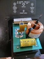
Before you go changing component values, have you verified that the Ultrasonic Bias Power Supply has been upgraded? The easy way to tell is if the red wire exiting the top of the air-core bias transformer has another wire wrapped around it. If not, I can send easy instructions.
The parts on the board match the latest list and location. The wire is wrapped around the HF transformer lead as shown.
How would just changing the transformer be enough? It's the DC voltage after the regulator pass transistor which affects the HV output.
If I increase only the transformer voltage all it does is increase the dissipation of the the pass transistor. it doesn't affect the maximum base voltage to the transistor which controls the oscillator output voltage ( in combination with the feedback picked up by the wire coil). I think I need to change both the transformer and Zener to have a high enough raw DC voltage to be able to increase the zener's voltage rating. I will replace the transformer ( and then if needed replace the zener with a couple of volts higher ( after I reset the pot to lowest value before testing).
- Home
- Loudspeakers
- Planars & Exotics
- Acoustat Answer Man is here