Hello,
I recently found a problem with my ESL. The copper strips which I put around the ESL for biasing the diaphragm turn green and do not conduct very well. Indeed the climate in my country is very humid. What should I do to prevent this oxidation?
Wachara C.
I recently found a problem with my ESL. The copper strips which I put around the ESL for biasing the diaphragm turn green and do not conduct very well. Indeed the climate in my country is very humid. What should I do to prevent this oxidation?
Wachara C.
I had given that problem some consideration when I built mine 7 years ago and decide to use aluminium foil tape.
They still work today and no corrosion problems have ever occured.
Resistance factor?
At an esl's voltages, it isn't going to make a bit of diffirence.
They still work today and no corrosion problems have ever occured.
Resistance factor?
At an esl's voltages, it isn't going to make a bit of diffirence.
Hi Jer,
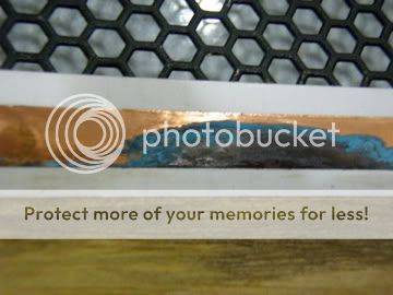
Thanks for your advice. I've never thought of that. Maybe that's what I should do. The attached picture shows how serious my problem is.
Wachara C.
Thanks for your advice. I've never thought of that. Maybe that's what I should do. The attached picture shows how serious my problem is.
Wachara C.
I like your stator material can give me the dimensions of the holes and such,I like the looks of hexagons better than circles and I think it would allow a more consistant thicker coating without closing them up as much.
I also had this in mind, that if I were to use copper, was to get a home gold plating kit to coat the copper with.
Maybe you could do that instead of having to tear everything apart.
Or if you do choose to redo everything the gold coating will not corrode and you can still easily solder to it, something you can't due too well with aluminium.
I was thinking of doing this to my tig wire stators before I clear coat them as copper is pretty but gold would be better with the added benifit of anticorrosion. jer
p.s. sodium hydroxide (lye) will clean that copper to a super bright finnish without etching or disolving it.
Last edited:
Sorry to hear about your problem with the copper, sometimes it seems that you really need a long fuse with these ESL's. 🙁
You could maybe try leaf gold? Might be tricky to contact to HV-supply though, but if you use foam tape and connect that to some sort of a terminal it might work. Don't really have any experience with that stuff, but I know it's pretty thin...
You could maybe try leaf gold? Might be tricky to contact to HV-supply though, but if you use foam tape and connect that to some sort of a terminal it might work. Don't really have any experience with that stuff, but I know it's pretty thin...
vmk,if that is real gold I would like to find a supplier here in the states.
I had found that web site a long while ago and the only true metal leaf I can get is pure copper or aluminium in sheet form.
It would be nice to get some of those 6mm rolls for some diy ribbons. jer
I had found that web site a long while ago and the only true metal leaf I can get is pure copper or aluminium in sheet form.
It would be nice to get some of those 6mm rolls for some diy ribbons. jer
Hi Jer,
The hexagon stators certainly look nice. But they might not have the hole size that you like to have. Here in Thailand, the smallest hole I can find is 6 mm and I think the holes are too big and the open area is too much. The efficiency is therefore quite low. I now have to use 9.6KV of bias voltage for my panel with 3 mm spacer to sound loud enough for me. I use 1:150 transformers and a 300 watts class D amp.
I'm thinking of using black ink to draw a line for biasing diaphragm instead of using copper. In my experiment, the conductivity is not too bad with this ink. What do you think?
Wachara C.
would it be wise to clear coat the copper ? or will that lock in moisture and deteriate anyway, or just keep an eye and keep em clean? never thought about that untill i saw the pics. Mav
Hi Mavric,
The problem is that you need to make the copper conductive. With clear coating, of course you can prevent the oxidation problem, but there won't be conductivity on the copper to bias the diaphragm.
Since you are making your new ESL, why not take this problem into your consideration and choose a nice and long lasting material for this purpose? Let's think about it.
Wachara C.
10-4, i have allready purchased the copper and was looking for a way to protect it, lithium grease,, something to coat copper with no adverse effects.
so YES, lets think about it. i have not apllied mine yet, so this will be good info for anyone reading.
so YES, lets think about it. i have not apllied mine yet, so this will be good info for anyone reading.
In mine I never used a border.
As long as I had contact with the coating and the diagphram charged up i had no problems what so ever .
But I do like the idea of a border for a extra measure,especialy with large panels.
I do recall however on a few of my first couple of try's the coating cracked or something. Losing contact near the frame and not charging.
I fixed that by using a heavier coat of licron around the border.
I recall thinking about getting some conductive spray paint instead of using copper or aluminium tape because i was worried about offsetting the center of the diagphram by 3 mil as you know this is a real issue when using a small d/s like in headphones.
Remember when you guys taught me about pva glue?
I got to brainstorming and dumped a bunch of graphite in a 1:8 water glue mixture and made a conductive paint.
I then thought, at that time, that this would be the perfect application for it .
I plan to try it on the new diagpharm to replace the one i burned up last week.
Along with the new lichron crystal clear i got also.
Another one I did was I used licron just for the border and graphite for the coating but i didn't much care for the graphite trick and never did it again.
I used that frame to test the shrinkage of the mylar and the strength of frame and burned that one up with the heat gun also.
Fun,Fun,Fun! jer
Last edited:
Perhaps you could try electroless nickel plating, as is sometimes done to protect circuit boards. The plating solution is commercially available. You'd just need to be able to submerge your copper tape in the solution to coat it.
Few
Few
Wachara: -Is the oxidation shown the only place you have it on the copper loop or is there other places that are oxidized as well?
I'm thinking if the problem is the glue used for the stators - you do not get it "air tight"!?
/R
I'm thinking if the problem is the glue used for the stators - you do not get it "air tight"!?
/R
Hi SM7UYL,
The oxidation occurs on all area around the ring. I did not glue the stators together. I screw them together. I don't think that it's air tight. Do you really think that it needs to be air tight?
Wachara C.
The oxidation occurs on all area around the ring. I did not glue the stators together. I screw them together. I don't think that it's air tight. Do you really think that it needs to be air tight?
Wachara C.
Do you really think that it needs to be air tight?
In your case - Yes, you provided the evidence your self! 😉
If you do not want to glue your stators together, you could perhaps try to coat your spacers with silicone on both sides off the copper strip(just a bit thicket than the foil) and let this be your "gasket" for the loop!
/R
Hi,
Failure of contact from copper strip to diaphragm is one of the most often to find reasons. You can paint the copper strip with the diaphragm coating. The conductive layer should be of lower resistivity than on the diaphragm itself. The rim of the copper strip is sensitive to breakdown through lowlevel flashovers. Things improve when the transit from the low resistive copper to the high resistive diaphragm happens gradually. This may be done with a thicker layer of coating or a different mixture of it. Someone suggested to use a strip of thin paper soaked in coating as a coupling device between the two different conductors. I think that this is a very smart idea, that hinders the strip´s oxidation and forms a long lasting conductive path. Things also improve when Your design doesn´t need high voltages. While certain coatings work perfectly well with lower voltages they might fail over time with higher voltages.
jauu
Calvin
In your case - Yes, you provided the evidence your self! 😉
If you do not want to glue your stators together, you could perhaps try to coat your spacers with silicone on both sides off the copper strip(just a bit thicket than the foil) and let this be your "gasket" for the loop!
/R
Hi SM7UYJ,
Thanks for your advice. I'll try it. 🙂
Wachara C.
Hi,
Failure of contact from copper strip to diaphragm is one of the most often to find reasons. You can paint the copper strip with the diaphragm coating. The conductive layer should be of lower resistivity than on the diaphragm itself. The rim of the copper strip is sensitive to breakdown through lowlevel flashovers. Things improve when the transit from the low resistive copper to the high resistive diaphragm happens gradually. This may be done with a thicker layer of coating or a different mixture of it. Someone suggested to use a strip of thin paper soaked in coating as a coupling device between the two different conductors. I think that this is a very smart idea, that hinders the strip´s oxidation and forms a long lasting conductive path. Things also improve when Your design doesn´t need high voltages. While certain coatings work perfectly well with lower voltages they might fail over time with higher voltages.
jauu
Calvin
Hi Calvin,
Do you mean that to use a sheet of thin paper soaked with coating material and put it on top of the copper strip (between the copper strip and the diaphragm)?
Wachara C.
- Status
- Not open for further replies.
- Home
- Loudspeakers
- Planars & Exotics
- Oxidation problem of copper strips in ESL