i originally posted this a few days ago on another forum:
-------------
By George Chkhartishvili
September 6, 2009
The purpose of this public post is to document my invention thereby establishing prior art for it.
Ultra-High performance loudspeakers must energize a diaphragm of large surface area in a manner that will:
1 - Minimize diaphragm flex throughout operating frequency range
2 - Maintain linear driving force throughout the range of excursion
The only technology to date that I believe has fully met these criteria is the electrostatic loudspeaker panel ( ESL ). ESL achieves this by having a driving force ( electrostatic field in that case ) that is UNIFORM IN 3 DIMENSIONS throughout the entire region of space where any part of the ESL diaphragm can find itself at any time.
ESL would have been perfect if not for two inherent problems:
1 - ESL loudspeakers provide a difficult load for an amplifier
2 - ESL loudspeakers must be very large to produce high output
Ribbon speaker is a competing technology which doesn't have the above 2 shortcomings of ESLs but also didn't have the advantage of driving force linear in 3 dimensions - until now.
The technology presented here essentially combines the benefits of the two technologies ( ESL and Ribbon ) without the shortcomings of either.
Physical design of linear ribbon transducer has a geometry similar to that of an ESL panel. This is the source of its inherent linearity and uniformity.
In the design presented here a ribbon panel ( can be of any height and any width, just as in an ESL speaker ) is situated between two magnets ( where the Stators would be in an ESL ). each magnet is shaped like a flat sheet ( of Neodymium or any permanent magnetic material ) with the direction of magnetization running not through, but ALONG the surface of the sheet. both magnetic sheets are magnetized in the same direction.
The magnetic field lines going through these magnets find their way back ( for the flux to complete the loop ) around the magnets but also between them, thus forming a magnetic gap. The flat magnets are perforated to allow sound to pass through ( just as the stators are perforated in an ESL ). In practice the perforated magnetic sheets can be replaced by 2-dimensional arrays of small magnets of any shape ! The array need only approximate the shape of a sheet. No steel is needed for the motor structure, just the permanent magnets.
The current flows in the ribbon panel ( thin, wide sheet of aluminum foil or any other suitable construction ) in a direction perpendicular to that of magnetic field lines in the gap. The resulting force is perpendicular to the plane of the ribbon and that of the flat perforated magnetic sheets.
Here is a finite element analysis simulation of a horizontal cross section of such a ribbon:
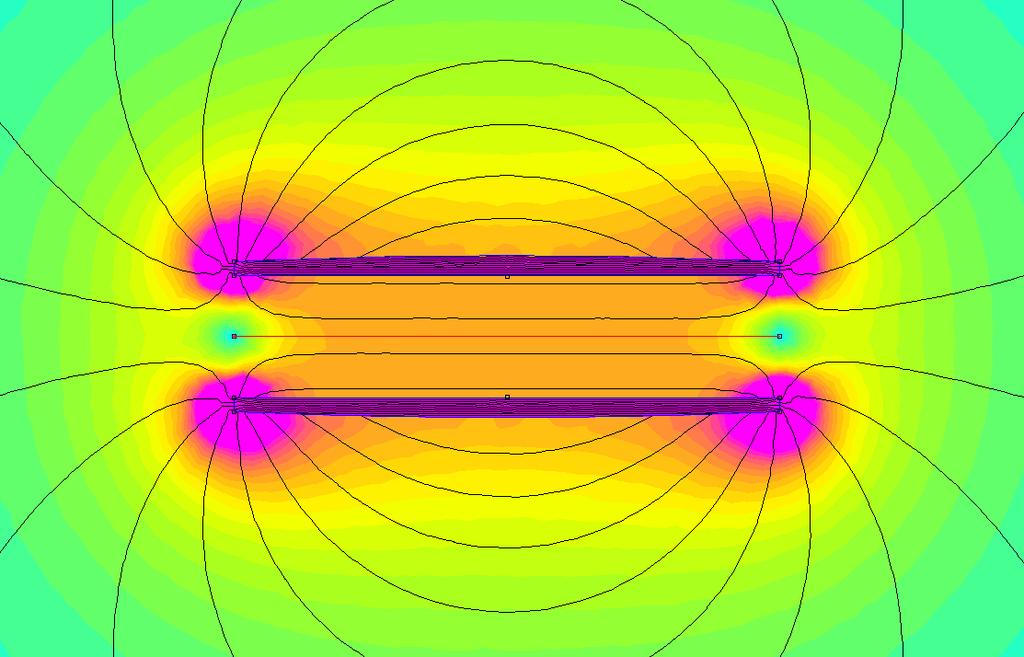
The two sheets of neodymium look like thin bar magnets in this image because it is a cross section. To understand this diagram imagine that you took a 2 meter tall, 4" wide ribbon, cut it in half and are looking at the cut from the ceiling. The thin horizontal red line denotes a plane where the ribbon surface would be situated. Here is a magnetic field magnitude plot through that red line:
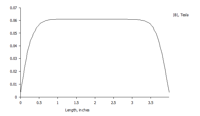
As you can see it is possible to create a wide region where field strength is uniform to a very large degree. This ensures that the entire surface of the ribbon is driven uniformly ( in this example using 4" wide neodymium sheets a ribbon of about 2.5" width would be uniformly driven ) ensuring minimum flex possible and therefore minimum amount of related distortions.
Observe now field uniformity along a different axis:
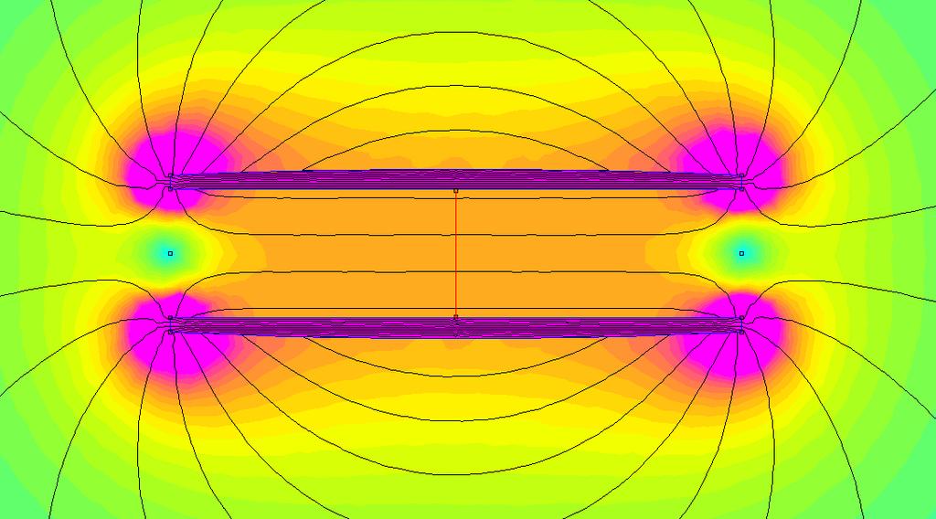 The thin red vertical line here represents the range of motion of the ribbon. Here is the corresponding plot of the normal ( perpendicular, or effective ) field intensity along that line:
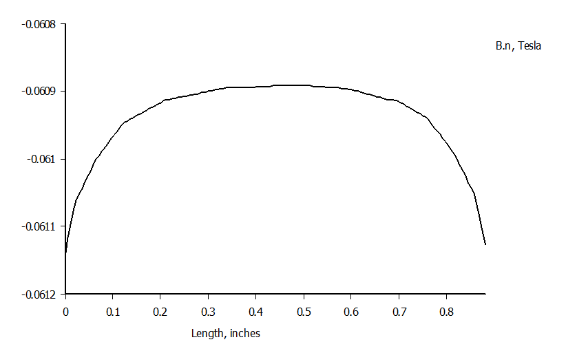
Uniformity in this plot is by far more important than in the previous one because any nonlinearity here will DIRECTLY translate into distortion. The graph doesn't seem particularly flat until you look at the scale to the left. 100*(0.0611 - 0.0609)/0.0611 = 0.3% The maximum deviation of normal ( perpendicular ) field intensity throughout the ONE INCH of peak mechanical excursion range is only 0.3% ! ! ! This linearity of 99.7% would in itself be impressive but in normal operation the excursion of the ribbon will be of course much smaller. The flat and symmetrical plateau in the middle of this curve means B field will be approximately 99.99% linear for normal range of excursions ! ! !
This number means the technology is theoretically capable of distortions as low or lower than the best audio amplifiers. But most importantly the inherent symmetry of the curve ensures that as excursion decreases nonlinearity tends towards zero.
To summarize PLUR driver is superior to:
ESL - because it is more efficient, compact and an easier load on the amplifier.
Push Pull Isodynamic - because the entire diaphragm can be a conductor that is uniformly energized
Traditional Ribbon: - because the B or BL curve ( force vs excursion ) is both linear and symmetrical in PLUR while it is neither linear nor symmetrical in a traditional ribbon. This potentially reduces distortion by orders of magnitude. This linearity is a function of a geometry that uses two parallel planes to set up a field between them. It is the same geometry that produces the same linearity in an ESL speaker but PLUR applies it to static magnetic ( as opposed to electrostatic ) field.
George Chkhartishvili
September 6, 2009
-------------
By George Chkhartishvili
September 6, 2009
The purpose of this public post is to document my invention thereby establishing prior art for it.
Ultra-High performance loudspeakers must energize a diaphragm of large surface area in a manner that will:
1 - Minimize diaphragm flex throughout operating frequency range
2 - Maintain linear driving force throughout the range of excursion
The only technology to date that I believe has fully met these criteria is the electrostatic loudspeaker panel ( ESL ). ESL achieves this by having a driving force ( electrostatic field in that case ) that is UNIFORM IN 3 DIMENSIONS throughout the entire region of space where any part of the ESL diaphragm can find itself at any time.
ESL would have been perfect if not for two inherent problems:
1 - ESL loudspeakers provide a difficult load for an amplifier
2 - ESL loudspeakers must be very large to produce high output
Ribbon speaker is a competing technology which doesn't have the above 2 shortcomings of ESLs but also didn't have the advantage of driving force linear in 3 dimensions - until now.
The technology presented here essentially combines the benefits of the two technologies ( ESL and Ribbon ) without the shortcomings of either.
Physical design of linear ribbon transducer has a geometry similar to that of an ESL panel. This is the source of its inherent linearity and uniformity.
In the design presented here a ribbon panel ( can be of any height and any width, just as in an ESL speaker ) is situated between two magnets ( where the Stators would be in an ESL ). each magnet is shaped like a flat sheet ( of Neodymium or any permanent magnetic material ) with the direction of magnetization running not through, but ALONG the surface of the sheet. both magnetic sheets are magnetized in the same direction.
The magnetic field lines going through these magnets find their way back ( for the flux to complete the loop ) around the magnets but also between them, thus forming a magnetic gap. The flat magnets are perforated to allow sound to pass through ( just as the stators are perforated in an ESL ). In practice the perforated magnetic sheets can be replaced by 2-dimensional arrays of small magnets of any shape ! The array need only approximate the shape of a sheet. No steel is needed for the motor structure, just the permanent magnets.
The current flows in the ribbon panel ( thin, wide sheet of aluminum foil or any other suitable construction ) in a direction perpendicular to that of magnetic field lines in the gap. The resulting force is perpendicular to the plane of the ribbon and that of the flat perforated magnetic sheets.
Here is a finite element analysis simulation of a horizontal cross section of such a ribbon:
The two sheets of neodymium look like thin bar magnets in this image because it is a cross section. To understand this diagram imagine that you took a 2 meter tall, 4" wide ribbon, cut it in half and are looking at the cut from the ceiling. The thin horizontal red line denotes a plane where the ribbon surface would be situated. Here is a magnetic field magnitude plot through that red line:
As you can see it is possible to create a wide region where field strength is uniform to a very large degree. This ensures that the entire surface of the ribbon is driven uniformly ( in this example using 4" wide neodymium sheets a ribbon of about 2.5" width would be uniformly driven ) ensuring minimum flex possible and therefore minimum amount of related distortions.
Observe now field uniformity along a different axis:
Uniformity in this plot is by far more important than in the previous one because any nonlinearity here will DIRECTLY translate into distortion. The graph doesn't seem particularly flat until you look at the scale to the left. 100*(0.0611 - 0.0609)/0.0611 = 0.3% The maximum deviation of normal ( perpendicular ) field intensity throughout the ONE INCH of peak mechanical excursion range is only 0.3% ! ! ! This linearity of 99.7% would in itself be impressive but in normal operation the excursion of the ribbon will be of course much smaller. The flat and symmetrical plateau in the middle of this curve means B field will be approximately 99.99% linear for normal range of excursions ! ! !
This number means the technology is theoretically capable of distortions as low or lower than the best audio amplifiers. But most importantly the inherent symmetry of the curve ensures that as excursion decreases nonlinearity tends towards zero.
To summarize PLUR driver is superior to:
ESL - because it is more efficient, compact and an easier load on the amplifier.
Push Pull Isodynamic - because the entire diaphragm can be a conductor that is uniformly energized
Traditional Ribbon: - because the B or BL curve ( force vs excursion ) is both linear and symmetrical in PLUR while it is neither linear nor symmetrical in a traditional ribbon. This potentially reduces distortion by orders of magnitude. This linearity is a function of a geometry that uses two parallel planes to set up a field between them. It is the same geometry that produces the same linearity in an ESL speaker but PLUR applies it to static magnetic ( as opposed to electrostatic ) field.
George Chkhartishvili
September 6, 2009
Attachments


Last edited:
Hi Borat,
Your invention is very interesting. Have you actually built one? I'm looking forward to seeing more of your progress. Thanks for sharing.
Wachara C.
🙂
Your invention is very interesting. Have you actually built one? I'm looking forward to seeing more of your progress. Thanks for sharing.
Wachara C.
🙂
no haven't built it. i just came up with the idea recently.
i am traveling right now ...
when i can have some peace of mind i will have to assess what building a prototype might involve. i never built any ribbons before so i can't say right now whether i will build one or not.
why don't you build one ?
🙄
i am traveling right now ...
when i can have some peace of mind i will have to assess what building a prototype might involve. i never built any ribbons before so i can't say right now whether i will build one or not.
why don't you build one ?
🙄
Hi Borat,
Your invention is very interesting. Have you actually built one? I'm looking forward to seeing more of your progress. Thanks for sharing.
Wachara C.
🙂
I second this. I hope to see much more about this as it develops.
May I ask a question? From the field line diagrams, I can only assume that a current carrying element -the ribbon - passes into the plane of the diagrams of the B field analysis? Another way to think of the design is that the ribbon sits within the field that would exist inside a hollow magnet. Am I correct?
You certainly get a superb uniformity. The overall field strength (as shown in the simulated configutation) is only a small fraction of what could be achieved with the same NdFeB magnets in the more common gap designs. However, I don't know what the field strength is like in systems such as the Magnepan speakers (no Neo magnets there, and wide spacings) so perhaps this configuration could be rather promising if sufficient BL product can be devised.
Ed
interestin
I'd love to see how this turns out.
In my work with magnetic materials (generally softer than NIB) I've noticed that the alignment you use tends to significantly shift the north poles internally (to lower the energy of the system). I'm not sure if this would always come out in simulation. Not insurmountable, but something to look out for if your uniformity is not what you exect.
May I ask a question? From the field line diagrams, I can only assume that a current carrying element -the ribbon - passes into the plane of the diagrams of the B field analysis? Another way to think of the design is that the ribbon sits within the field that would exist inside a hollow magnet. Am I correct?
the ribbon is where the thin red line is :
in a 3D view it would be like this ( diagram by NeoDan from another forum )
so in this diagram you see two arrays of neodymium bar magnets. and the ribbon element would go right between the two arrays.
You certainly get a superb uniformity. The overall field strength (as shown in the simulated configutation) is only a small fraction of what could be achieved with the same NdFeB magnets in the more common gap designs. However, I don't know what the field strength is like in systems such as the Magnepan speakers (no Neo magnets there, and wide spacings) so perhaps this configuration could be rather promising if sufficient BL product can be devised.
Ed
Attachments

compared to a regular ribbon which, admittedly, would have a much stronger field, my driver would have much larger surface area because it is able to create a field across a wide ribbon.
in a conventional ribbon as you try to make it wider the field strength drops dramatically. so much so that perhaps 99% of all ribbons stay at or below 1" wide. but in PLUR there is no strong relationship between ribbon width and field strength.
field does get a tiny bit weaker in the middle of the gap and stronger at the edges ( thats why in my simulation my magnet is about 5% thicker in the middle than on the sides ) but this effect is very minor. in other words unlike in a conventional ribbon you could double the ribbon width and lose very little field, maybe 5%. you can make it as wide as you want basically. you can make it a foot wide. and doubling the width automatically gives you extra 6db of output. so compared to a conventional ribbon PLUR can use its width to compensate for weaker field to bring output back up.
compared to magnepan it has all of the diaphragm conducting. if magnepan has 1/3 of its moving mass in conductor the it will need 3 times the field strength for same output.
Could be a really cost-effective way of building ribbons. It really could be that I´ll become a ribbon builder now.
http://cgi.ebay.de/200-Neodym-Magne...ash=item25567fbc94&_trksid=p4634.c0.m14.l1262
http://cgi.ebay.de/200-Neodym-Magne...ash=item25567fbc94&_trksid=p4634.c0.m14.l1262
Since these line of force do not cut thru the ribbon anywhere,
how is it a current applied to the ribbon supposed to move it?
how is it a current applied to the ribbon supposed to move it?
Since these line of force do not cut thru the ribbon anywhere,
how is it a current applied to the ribbon supposed to move it?
its gonna move because the ribbon is submerged in the field and because the lines are perpendicular to the direction of current and perpendicular to the direction of excursion.
just consider the fact that the force in a ribbon or a voice coil is felt by electrons. and electrons basically are just points. if i drew the ribbon sideways so the lines cut through it - it wouldn't make any difference for the electrons inside.
consider the motion of individual electrons and it all works out ...
Could be a really cost-effective way of building ribbons. It really could be that I´ll become a ribbon builder now.
http://cgi.ebay.de/200-Neodym-Magne...ash=item25567fbc94&_trksid=p4634.c0.m14.l1262
build a tiny prototype 🙂
the ribbon is where the thin red line is :
in a 3D view it would be like this ( diagram by NeoDan from another forum )

so in this diagram you see two arrays of neodymium bar magnets. and the ribbon element would go right between the two arrays.
Ah, OK, so the ribbon is seen edge on, with the current "vector" perpendicular to the plane of the diagram. The extended design is a vertical slatted array of magnets, within which the ribbon is suspended. I understand better now - thanks for the clarification.
I wonder how your efficiency and frequency response will work out, since driving force is proportional to current, and the increased area raises the mass of the ribbon element. Also, the wide ribbon will have a very low DC resistance and overall impedance, so a matching transformer would seem necessary.
Please do not take my comments as destructive - This is an interesting design, and there is a lot to consider in its implementation!
Ed
Ah, OK, so the ribbon is seen edge on, with the current "vector" perpendicular to the plane of the diagram. The extended design is a vertical slatted array of magnets, within which the ribbon is suspended.
correct.
the wide ribbon will have a very low DC resistance and overall impedance, so a matching transformer would seem necessary.
yes impedance would be very low, but let's not make any assumptions about how it will be driven.
there is plenty of room for innovation in amplifiers as well. a transformer between amp and ribbon would be an off-the-shelf solution.
one option would be to have a transformer internal to the amp with NFB running around the transformer. McIntosh amplifiers for example use transformers even though they are solid state.
transformer is more linear than gain devices inside the amp anyway. it is only a matter of properly integrating it into the overall gain structure as opposed to just mindlessly connecting it between the amp output and the driver.
Absolutely. I have an EL34 amp kit that takes feedback from the secondary side of the amp, and see no problem with that approach. A dedicated amp is no bad idea for a unique speaker design. Moreover, the step-down transformer for a ribbon driver perhaps is somewhat less difficult to design than the high impedance transformation ratio needed for valve amps. Certainly there will be a way to drive it safely.
I think the interesting physics comes in where we consider efficiency, frequency response, directivity etc. as a function of ribbon width. It is width, after all, that is the parameter with which this design offers most flexibility.
Ed
Hi,
hopefully i do not misunderstand the concept.
But from what i understand, this ribbon might have significant issues with cavitiy resonances in the high frequency range, due to the array of the magnets
Capaciti
hopefully i do not misunderstand the concept.
But from what i understand, this ribbon might have significant issues with cavitiy resonances in the high frequency range, due to the array of the magnets
Capaciti
Hi,
hopefully i do not misunderstand the concept.
But from what i understand, this ribbon might have significant issues with cavitiy resonances in the high frequency range, due to the array of the magnets
Capaciti
yes above a certain frequency the magnet array would not be completely transparent acoustically.
how significant is that effect ? most metal dome tweeters for example employ a phase lens, such as this:
An externally hosted image should be here but it was not working when we last tested it.
and such a phase lens operates mostly above 10 khz.
so thats about the size the magnet should be to have a significant effect acoustically. however the magnets could be made thinner than this and push undesirable effects to mostly above 20 khz.
what i think though is that the optimum application for this transducer ( of course this remains to be verified ) would be vocal range using a line source about 3" wide.
for narrow ribbon widths and small excursions a conventional ribbon design will be more efficient. it will also not have that acoustical transparency issue at high frequencies. therefore i think it would be a good idea to hand off the highest frequencies ( 5 khz + ) to a conventional true ribbon. because you would probably want a narrower ribbon to cover the top octave anyway.
so my vision is a 3-way along these lines:
An externally hosted image should be here but it was not working when we last tested it.
with PLUR being a wide-band midrange/vocal driver ( say 300 hz - 8 khz )
Last edited:
Gold ribbon Cocepts in the 80's used a somwhat similatar though - vertical oriented magnets left and right in front and behind the ribbon. Their real innovation was to use vapor deposition of gold on a Kevlar membrane to get the impedance high - very thin coating. 4 ohms over 8 feet of ribbon conductor.
- Status
- Not open for further replies.