Hi all,
been testing my 1st prober esl's.
Made them with idea of a 2-way esl + hybrid woofer (still to come). My wife likes to listen too, that's why I decided to try 2-way and hopefully end up with larger hot spot.
Problem is that in 2-way mode, bigger panel filtered with series resistor, the speakers doesn't sound as good as when driven both element's full range without any filtering.
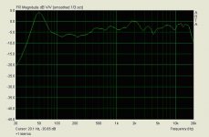
Lots of accuracy is lost noticeable especially in "stereo image". Still 2-way frequency response looks quite fine:
Any input? Yes, I know it would have been good to ask first, but I like to learn from my own mistakes thank you.
Few pictures of the project so far with comments can be found: here.
been testing my 1st prober esl's.
An externally hosted image should be here but it was not working when we last tested it.
Made them with idea of a 2-way esl + hybrid woofer (still to come). My wife likes to listen too, that's why I decided to try 2-way and hopefully end up with larger hot spot.
Problem is that in 2-way mode, bigger panel filtered with series resistor, the speakers doesn't sound as good as when driven both element's full range without any filtering.
Lots of accuracy is lost noticeable especially in "stereo image". Still 2-way frequency response looks quite fine:
An externally hosted image should be here but it was not working when we last tested it.
Any input? Yes, I know it would have been good to ask first, but I like to learn from my own mistakes thank you.
Few pictures of the project so far with comments can be found: here.
Last edited:
Hi all,
been testing my 1st prober esl's... Still 2-way frequency response looks quite fine:
An externally hosted image should be here but it was not working when we last tested it.
Any input?
Although it has a rather smooth monotonic upwards tilt, there is obvious SPL deficiency up to 500Hz. 5 dB max difference not minding the troughs, else its 10-15dB. That translates to human ear in diminished midbass volume perception. Since the power range of an orchestra is at 200-800Hz, even if you don't care much about bass, there will be thin perception of any music and vocals. Since the ESLs never have sensitivity to spare so to tilt down the trend with a line level filter, better make an inverse one, tilting up from about 500Hz downwards 50Hz by 5dB. If your membrane travel margin will not allow you much undistorted SPL with that approach, then midbass capable, mains flanking biamplified columns can come to rescue. Or double subs with forward facing woofers with no breakups up to 1kHz and crossing at 400-500Hz. Normal subs good up to 100-150Hz will leave a void in to the much fundamental 200-500Hz area for your music never to sound fleshed out and with realistic size. Big room there, excellent ESLs, its worth the effort for a full spectrum big scale hybrid system. Another approach, more economic in xmax and gear, would be to tone up from 500Hz down to 150Hz the mains, cut them abruptly, and then introduce a single good sub crossing at 150Hz.
Hi all,
been testing my 1st prober esl's.

Made them with idea of a 2-way esl + hybrid woofer (still to come). My wife likes to listen too, that's why I decided to try 2-way and hopefully end up with larger hot spot.
Problem is that in 2-way mode, bigger panel filtered with series resistor, the speakers doesn't sound as good as when driven both element's full range without any filtering.
Lots of accuracy is lost noticeable especially in "stereo image". Still 2-way frequency response looks quite fine:

Any input? Yes, I know it would have been good to ask first, but I like to learn from my own mistakes thank you.
Few pictures of the project so far with comments can be found: here.
*Hello ,Could you explain more , is your bandpass filter made up of just resistors ?
*Is it you are running said tweeter panel full range ?
*Do you have seperate power supply or are all panels feeding off the same ?
Regards,
Ok, thanks all. I'm going to make new version with only one ESL-element per channel. Will also use bigger air cap (now only 1.2mm), one of the speakers started to leak like crazy and died  ...
...
Before it went I managed to test them with dynamic basses, electronic xover at 330Hz 24db/oct. Integration of esl and dynamic bass was horrible! I want to go much lower with ESL, so I need bigger panel and more room for the Mylar to move?
Size of the new ESL-panel will be 320*1200mm (stator cut off's and frames dictate that size). How low will that size of panel go if I use let's say 2mm air cap? Any successions on the air cap size?
...Before it went I managed to test them with dynamic basses, electronic xover at 330Hz 24db/oct. Integration of esl and dynamic bass was horrible! I want to go much lower with ESL, so I need bigger panel and more room for the Mylar to move?
Size of the new ESL-panel will be 320*1200mm (stator cut off's and frames dictate that size). How low will that size of panel go if I use let's say 2mm air cap? Any successions on the air cap size?
Try open H frame dipole bass. Its the enclosure first ms smearing that makes it too obvious when crossing at 350 to 500Hz to a an open frame ESL. High Qts large professional woofers without early strong break up are needed for H frame, will integrate easier than typical subs. Now if you go for larger membrane area, I am not an expert at all in ESLs, somebody else might answer your questions, I am just thinking of more difficult to control resonant modes in several directions if a membrane is getting large.
Ok, thanks all. I'm going to make new version with only one ESL-element per channel. Will also use bigger air cap (now only 1.2mm), one of the speakers started to leak like crazy and died
Before it went I managed to test them with dynamic basses, electronic xover at 330Hz 24db/oct. Integration of esl and dynamic bass was horrible! I want to go much lower with ESL, so I need bigger panel and more room for the Mylar to move?
Size of the new ESL-panel will be 320*1200mm (stator cut off's and frames dictate that size). How low will that size of panel go if I use let's say 2mm air cap? Any successions on the air cap size?
My frame size is 300 x 1200 mm. Using 2 mm spacer, I get around 36Hz.
Wachara C.
My frame size is 300 x 1200 mm. Using 2 mm spacer, I get around 36Hz.
Wachara C.
Hey, that sounds more like it. I need to redo the leaking stator anyway and now that we have bigger living room than what we had when I started the project I might as well go little bit bigger
.I made dipole bass units once for my little Magneplanar's and they were nice match for them. Have to start to selling the idea for my wife
cheers,
Vesku
Hey, that sounds more like it. I need to redo the leaking stator anyway and now that we have bigger living room than what we had when I started the project I might as well go little bit bigger
I made dipole bass units once for my little Magneplanar's and they were nice match for them. Have to start to selling the idea for my wife
cheers,
Vesku
Hi Vesku,
I meant to say that my stator size was 300x1200.
I put three little spacers (25mmx25mm) in the middle of the stator instead of a long one like yours. I think that it helps the diaphragm to vibrate easier.
Wachara C.
OK, now they are redone. 1-way and 2mm air cap. New stator dimension is 1250*305. The Mylar tension is lower, about 800g with ER-tension gauge.
The bigger size of the stator seems to be too much for my toroidal transformers, highs go down before 20kHz, but as I'm a half deaf it's not a big problem.
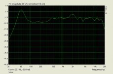
Had a little testing session with the transformers, there's a very big differences in the performance above ~12 kHz even if you just alter the primary winding by one round. Is it because the resonance freq of the trannys is below 20kHz? With a higher transfer ratio I get highs cut off earlier. With a low ratio the high freq resonance gets really big. The freq plot attached below is with the "right ratio" and 1 Ohm series resistor. Ratio is some where around 80, 5.5V to 230V... Some of the highs may be off because my extra long RCA-cables and crappy sound card...
I'm using Winamp and EQ-software . It's a pretty nice and easy way to find the sound you are after. Although all of the High End purists here probably don't agree
Obviously I want to get rid of the bass resonance, now I'm using about 60uF series capasitor to cut of lows (from about 100Hz). What is the prober way to take care of the bass resonance?
With the EQ-software I have tweaked +6dB's at 80Hz and sloping down to 450Hz (0dB) and speakers sound quite nice now (I have to do more listening before making my final call, I'm chancing the setting all the time...). What's the best way to do a similar equalising with passive components? I have done a few other ups and downs with the software, but I guess there's no easy way to do them with passive stuff. I wish I had mine Behringer parametric equaliser (feedback destroyer) with me here in NZ...
Now I need a beefier amp as well...
An externally hosted image should be here but it was not working when we last tested it.
The bigger size of the stator seems to be too much for my toroidal transformers, highs go down before 20kHz, but as I'm a half deaf it's not a big problem.
Had a little testing session with the transformers, there's a very big differences in the performance above ~12 kHz even if you just alter the primary winding by one round. Is it because the resonance freq of the trannys is below 20kHz? With a higher transfer ratio I get highs cut off earlier. With a low ratio the high freq resonance gets really big. The freq plot attached below is with the "right ratio" and 1 Ohm series resistor. Ratio is some where around 80, 5.5V to 230V... Some of the highs may be off because my extra long RCA-cables and crappy sound card...
I'm using Winamp and EQ-software . It's a pretty nice and easy way to find the sound you are after. Although all of the High End purists here probably don't agree
Obviously I want to get rid of the bass resonance, now I'm using about 60uF series capasitor to cut of lows (from about 100Hz). What is the prober way to take care of the bass resonance?
With the EQ-software I have tweaked +6dB's at 80Hz and sloping down to 450Hz (0dB) and speakers sound quite nice now (I have to do more listening before making my final call, I'm chancing the setting all the time...). What's the best way to do a similar equalising with passive components? I have done a few other ups and downs with the software, but I guess there's no easy way to do them with passive stuff. I wish I had mine Behringer parametric equaliser (feedback destroyer) with me here in NZ...
Now I need a beefier amp as well...
Attachments
Yep, tried with out series resistor as well, but I get quite nasty resonance peak if there's no series resistor. Now I have 0,5 Ohm and that seem to be the best value in my system.
Only difference in pictures below was that I did put one more round to the primary. It seems that in my set up the step up ratio makes the biggest difference how the highs behave.
But the speakers sound really nice, that's the main thing, I think. Need to start a woofer project next, dipoles... Well, I will first wait for couple of weeks and see are these ones still alive...
Attachments

We'll see tomorrow, I'll try to kill the resonance with a same value resistor
The stators are about 1.3nF, measured with a cheap DMM.
I used these transformers: 9 + 9 50VA Toroidal Transformer : Discount Electronics and unwinded the 9V side.
One of them shorted, I don't know what exactly happened. It was working fine with the speaker, but when I hooked it up to 230AC to check what the transfer ratio was after unwinding the secondary, it shorted the "230AC side". Rest of the three worked fine with 230 AC test. I might have damaged the winding some time through the process.
The stators are about 1.3nF, measured with a cheap DMM.
I used these transformers: 9 + 9 50VA Toroidal Transformer : Discount Electronics and unwinded the 9V side.
One of them shorted, I don't know what exactly happened. It was working fine with the speaker, but when I hooked it up to 230AC to check what the transfer ratio was after unwinding the secondary, it shorted the "230AC side". Rest of the three worked fine with 230 AC test. I might have damaged the winding some time through the
process.Hi,
as CR You could start with a peaking Highpass of 2nd order. Fpeak ~80Hz. this does basically the same as Your EQ does now. It ´pulls down´ the high peak at Fs and fills the dip above the peak.
To get values measure the impedance of the system and the amplitude repsonse and simulate for example with LSP-Cad or similar.
Read thread http://www.diyaudio.com/forums/planars-exotics/64620-ping-calvin.html Multidoc4 describes exactly what You could try.
jauu
Calvin
Hi Vmk,
looks nice !
At which distance you measured your system ?
If you measure at about 40" distande frequency response should show a linear and constant loss of sound pressure from low to high frequency. The difference should be about 10 dB since your room looks quite undamped.
The current plot indicates an anemic lower midrange and maybe Crying sound of voices.
Try a 220µF capacitor in serie to the stepup and bridge it with a resistor. Variation of the resitor value will enable constant lowering of pressure towards the high frequency. The value is difficult to predict, maybe start with 4,7 ohms.
Capaciti
Hi,
Read thread http://www.diyaudio.com/forums/planars-exotics/64620-ping-calvin.html Multidoc4 describes exactly what You could try.
jauu
Calvin
Thanks a lot for pointing out this good thread!
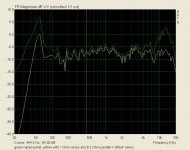
After installing the impedance correction resistor (8.2 Ohm) no change to output, but huge difference how the HP-capacitor acts. Now I need to use bigger series capacitor (200uF). It don't cut off the resonance anymore, but it acts like a prober HP-filter now.
Next I need to do the notch and the RL. That's going to be a bigger job, with the impedance measurements and learning how to use a new software. Hmm, as I'm lazy, is there any way to get away with a trial and error method with the notch and RL?
The 2kHz peak vanished when I moved the measurement point a bit higher... Not a spooky thing after all
My measurements are from about 10cm away from the speaker.Just had a quick look at the impedance measurement with ARTA and seems to be pretty straight forward, I'll try to get that done next. Just need to do the "voltage probe"...
Below a plot showing where I'm now with this never ending tweaking process. Will try with a bit larger capacitor later, but now I will listen some music
Attachments
- Status
- This old topic is closed. If you want to reopen this topic, contact a moderator using the "Report Post" button.
- Home
- Loudspeakers
- Planars & Exotics
- 2-way esl