It is about coating, as well....
To limit the latter one have to increase the distance between the widings.
This happens naturally in layer by layer wound HV secondary i.e. turns with the higher potential are the farthermost ones (from the core or LV primary).
Please be aware, that having few kV of AC voltage on the ordinary or "standard" power transformer at higher frequencies is OK from electromagnetic point of view.
BUT the same voltage at 5 to 20 kHz can and will easily develop barrier discharge inside or outside the HV winding, killing you trafo.
Recommended coil former thickness at 3kV AC is 5 mm, that is: "solid" dielectric. Creepage distance shall be substantial as well...
Exception would be kilowatt range old public address tube amplifier. No HI-FI frequency range there for sure
Listen to Calvin about the spacing.
BTW HV trafos often painted with dissipative coating similar to one used for membrane.
Alex
P.S. Design and fabrication of, let's say, GOOD full range output transformer for tube amplifier is tricky at best. ESL one with ratio 5 to 10 times higher - you've got the idea
Well, high voltage transformers usually do not have "simple" or "audio transformer like" interleaving due to high voltage between primary and secondary and assosiated capacitive (displacement) current.Hi JonasKarud,
Thanks again for the details of the windings. I'm very surprised to hear that there was no interleavings. In that case I guess there is no paper between each layer of the winding, is there?
Wachara C.
To limit the latter one have to increase the distance between the widings.
This happens naturally in layer by layer wound HV secondary i.e. turns with the higher potential are the farthermost ones (from the core or LV primary).
Please be aware, that having few kV of AC voltage on the ordinary or "standard" power transformer at higher frequencies is OK from electromagnetic point of view.
BUT the same voltage at 5 to 20 kHz can and will easily develop barrier discharge inside or outside the HV winding, killing you trafo.
Recommended coil former thickness at 3kV AC is 5 mm, that is: "solid" dielectric. Creepage distance shall be substantial as well...
Exception would be kilowatt range old public address tube amplifier. No HI-FI frequency range there for sure
Listen to Calvin about the spacing.
BTW HV trafos often painted with dissipative coating similar to one used for membrane.
Alex
P.S. Design and fabrication of, let's say, GOOD full range output transformer for tube amplifier is tricky at best. ESL one with ratio 5 to 10 times higher - you've got the idea
Last edited:
Hi,
the Quad (63 and it´s heirs) transformer can be rather simple wound, because it sees just a small part of the membrane, hence a small capacitive load. So even elevated values of stray inductance in the tranny don´t limit the response within the audio band. The limitations with such a concept are poor dynamics, because of small membrane area and losses within the tranny. This doesn´t even take the current steering into account which Quad achieves by large valued series resistors. Cancellation of the losses over those resistors requires an even higher U than that needed for simple voltage steering. With voltage steering the Quad needed probabely just half the U.
jauu
Calvin
Agreed,Hi,
the Quad (63 and it´s heirs) transformer can be rather simple wound, because it sees just a small part of the membrane, hence a small capacitive load. So even elevated values of stray inductance in the tranny don´t limit the response within the audio band. The limitations with such a concept are poor dynamics, because of small membrane area and losses within the tranny. This doesn´t even take the current steering into account which Quad achieves by large valued series resistors. Cancellation of the losses over those resistors requires an even higher U than that needed for simple voltage steering. With voltage steering the Quad needed probabely just half the U.
jauu
Calvin
still the secondary sees full frequency range - and problems I tried to mention are not about transfer function but rather about general construction and unsuitability of general purpose transformers for relatively high voltage...
and if Ls together with stator capacitance resonates within audio range, then the real fun begins.
Alex
Hi,
the quad stepups are very sophisticated. Taking in account the high stepup ratio, they did a very good job.
The capacity of a segmented ESL, noway if Quad ore audiostatic or Acoustat ist rather low compared to the parasitic capacitiy of the secondary winding of a worse made stepup. Its easy to find out. Check the impedance of any transformer without the ESL-load and most designs wont exceed 15 Khz, due to stray inductivity and parasitic capacitiy of the secondary winding.
This the reason the quad transformers are designed for lowest capacity as possible and this requires a lot of layers and insulation between each layer. In addition you need low dielectric insulation to keep capacitiy low. So forget about standard materials like Polyester foil.
A stepup with 1:150 ratio can drive 400pF panels up to 20khz if designed properly.
Capaciti
Hi,
This the reason the quad transformers are designed for lowest capacity as possible and this requires a lot of layers and insulation between each layer. In addition you need low dielectric insulation to keep capacitiy low. So forget about standard materials like Polyester foil.
Capaciti
It is also important how QUAD hooked their transformers up, with the end of the secondary closest to the primary connected to the center tap and the end of the secondary furthest from the primary hooked up to the panel. This minimizes that capacitive loading between the transformer windings.
I had asked a local transformer manufacturer about using polypropylene film for insulation in my transformers instead of the usual Polyester. This would reduce the secondary winding capacitance and primary-to-secondary capacitance by 30%. I was told that it's use was not recommended in HV applications. He said that it would fail due to tracking and corona issues which PE is much more resistant to. I thought that since PP was the dielectric of choice for HV capacitors it would work well.
Perhaps a moderator might move all these transformer related posts out if this coatings thread and into its own step-up transformer design thread.
Last edited:
I just finnished refurbishning one of my little panels today and I got to use techspray's new licron crystal clear.
It seems to work very well indeed.
It seems to be the same as the old licron except that it is much much finer.
With only a slight haze is noticeable from a refelction off of the mylar,otherwise it is see through.
I don't have any resistance measurement yet as I don't have a good meter at the moment.
Also I used a graphite charge ring made out of pva glue ,water,grapite and a drop or two of dawn dish detergent to help as a wetting agent.
This also worked great.
Tommorrow I will put the thing through some stress testing and see how it holds up. jer
Attachments
So far I have not had any major problems yet, except, for the typical amplifier ones I have been having.
The refurbished panel sound is slightly more better than the other one as there are some subtle differences in construction,namely the difference in open area.
But with the two of them together gave me some added db's in spl.
This allowed me to sit back and enjoy some music with out having to reset the amp constantly for a change.
And with only using one transformer core.
But the low end response wasn't where it needed to be because of it.
But it worked!
I will be reworking the other panels as well.
I would have to say that licron crystal is a wonderful product (although not a diy mixture) for diagphram coating and it will be some time in order to determine it's longevity.
The original formula never failed me in seven years as the panels have seen some harsh weathering condtions (even light mud and grit) and tossed around alot just for the purpose of testing durablity.
I just took them and brushed them off and shook the dirt out of them and they (both designs) worked with out a hitch and without having to take them apart either.
I'll try to get some resistance measurements some time in the future .
After I get a new meter.
p.s. And of course the tweeter is disconnected ,but I didn,t even use the woofer in todays testing as i was running the esl's fullrange above 80 hz .jer
Attachments
Last edited:
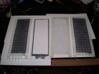
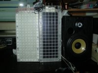
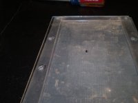
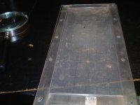
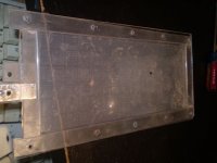
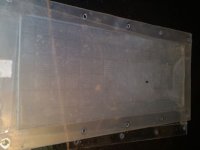
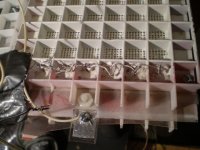
I took the white panel apart today to investigate why I was hardly getting any extreme high end output compard to the newly refurbished black one.
This is the first time it has ever been apart since it was built seven years ago.
Even though it worked,the dirt inside shows the abuse it has endured.
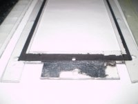
First I am going to clean the diagphram and put it back together and see if this restores the high end.
But I am still going to replace the diagphram and coating due to the burn hole and the coating (old original licron formula) seems to be quite thick.
This extra mass maybe the very reason for the loss of the high end response.
Also the stators are going to get a few more coats too, as they are not holding up to the new bias supply as well as the black ones I just redid.
Close but not enough.
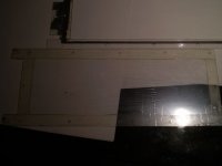
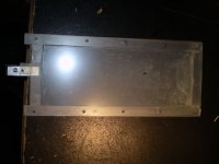
You will notice that one stator is longer than the other as this was a fluke when made it.
This one was the second one I ever built and served as the best bed for diagphrams ,coatings and d/s spacings ,for the rest of my designs.
This is the first time it has ever been apart since it was built seven years ago.
Even though it worked,the dirt inside shows the abuse it has endured.
First I am going to clean the diagphram and put it back together and see if this restores the high end.
But I am still going to replace the diagphram and coating due to the burn hole and the coating (old original licron formula) seems to be quite thick.
This extra mass maybe the very reason for the loss of the high end response.
Also the stators are going to get a few more coats too, as they are not holding up to the new bias supply as well as the black ones I just redid.
Close but not enough.
You will notice that one stator is longer than the other as this was a fluke when made it.
This one was the second one I ever built and served as the best bed for diagphrams ,coatings and d/s spacings ,for the rest of my designs.
Attachments
ger, you are doing a very fscinating project, i have one question? what would it take to make a di-pole surround sound with this? its small. does 180 degree sound, small, and one speaker. please give me your thoughts.
tradition is using conventional spk wired out of phase and they are very large. I spoke with you a little on this subject. can you kindly look up the most expensive dipole surrround spk and compare to your credit card size or maybe larger esl's. I have a feeling there is something there.
Going to la la land, but will send you my idea of powering these small esl with a "five wire" . two "spk" two "bias" one "diag"
this will be confusining to some, so a picture is worth a thousand words. please quote this as i have allready have a diag for ya.
I need some kind of surround sound, call , email, text, this is a unique idea, very simple.")
tradition is using conventional spk wired out of phase and they are very large. I spoke with you a little on this subject. can you kindly look up the most expensive dipole surrround spk and compare to your credit card size or maybe larger esl's. I have a feeling there is something there.
Going to la la land, but will send you my idea of powering these small esl with a "five wire" . two "spk" two "bias" one "diag"
this will be confusining to some, so a picture is worth a thousand words. please quote this as i have allready have a diag for ya.
I need some kind of surround sound, call , email, text, this is a unique idea, very simple.
So far I have not had any major problems yet, except, for the typical amplifier ones I have been having.
The refurbished panel sound is slightly more better than the other one as there are some subtle differences in construction,namely the difference in open area.
But with the two of them together gave me some added db's in spl.
This allowed me to sit back and enjoy some music with out having to reset the amp constantly for a change.
And with only using one transformer core.
But the low end response wasn't where it needed to be because of it.
But it worked!
I will be reworking the other panels as well.
I would have to say that licron crystal is a wonderful product (although not a diy mixture) for diagphram coating and it will be some time in order to determine it's longevity.
The original formula never failed me in seven years as the panels have seen some harsh weathering condtions (even light mud and grit) and tossed around alot just for the purpose of testing durablity.
I just took them and brushed them off and shook the dirt out of them and they (both designs) worked with out a hitch and without having to take them apart either.
I'll try to get some resistance measurements some time in the future .
After I get a new meter.
p.s. And of course the tweeter is disconnected ,but I didn,t even use the woofer in todays testing as i was running the esl's fullrange above 80 hz .jer
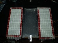
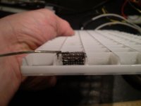
hi i whas wondering what ur stator whas made of ?, it looks real nice and verry small holes and lots of it. what is it, is it? PCB ??
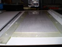
I put the white panel back together today.
By just cleaning the diaghram and adding a few more coats of clear acrylic paint seemed to restore the brilliance and highend that was lacking.
Although it did become unstable due to the 1/4"x3/8" burn hole in the mylar with too high of bias voltage.
Both panels seemed to match up to the woofer better than a single panel did in previous tests and seemed to even out the power difference between the two to be equal.
With this thread being about coatings, my observations of the two panels were that they were close but not the same ,with a very very subtle and slight difference in sound between the two.
The white panel seemed to be 1db to 2db more efficiant than the black panel.
It is possible that it might have a smaller d/s spacing by as much as .010" to .015" which can account for this.
The black panel which has a much thinner coating (licron crystal) compared to the white panels coating (original licronT) seemed to have a more delicate sounding high end with a little more finess than the white panel.
this seems to be the effect that everybody is claiming to hear, by using the thinnest and lightest materials available.
I will be able to investigate this further once I mend the connections on the other black panel as they are exactly identical physicaly except now the coatings are different.
All of the panels use .25 mil mylar. jer
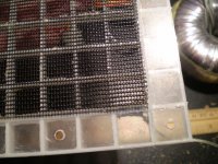
The stators are made from common aluminium window screen.
The black ones were double powder coated and then recently sprayed with a few coats of clear acrylic paint.
And the white ones are the same except they are just plain painted with various types of paint.
The next one I do will have a proper paint structure of primer,base coat and clear coat.
If I don't get the proper insulating factor I'll go back to powder coat and clear coat. jer
Aluminum wire as used in your bug screen will have a good coat of oxide on the wire surface so you really don't need a primer. You can give the screen a shot of paint for color then topcoat with clear. Use high gloss paints (your color coat too) as they will have the highest solids content. Clear hi gloss top coat will give you the most insulation that you can get with a given paint due to the solids content. I think that urethane will probably yield the highest dielectric strength but you might find some other materials that are as good without getting into specialty stuff that will cost an arm and a leg. Lots of light wet coats is the way to go to build up a good layer of insulation.
I did build panels like this but it took a while to get the paint viscosity adjusted so I did not end up clogging the screen. I then had some powder coated and went through a similar situation. After much effort I just figured that I could buy wire with a perfect and tested dielectric for a fraction of the money and just worry about sticking down to a louvre. I did not look but I am curious to know how you terminated your screen? On the ones I built I made one solder joint to a lead wire and then I took a little sand paper and cleaned the outside edge of the length of the screen and ran a bead of nickle print along the edge to make sure I was getting charge all along the length of the stator then I painted the whole thing up. Worked ok but I was always feeling worried about all those wire contact points and all that Aluminum oxide which is a good insulator. Sounds like you have had really good performance over a lot of years so perhaps my concerns were not justified.
Back in the 80's David Lang published a few articles in Speaker Builder. David used bug screen for his stators on louvre but he did not bother to insulate the screen. He simply used two diaphragms with the conductive coating on the inside and let the Mylar be the insulation. Not a bad idea as it really made the construction simple. I suppose that with the thin films available one could take it a step further by installing an extra set of diaphragms spaced over the bare uninsulated stators as well as an insurance layer of insulation. Lots of extra mass but it could be made to work just a thought. Nice to see you do such a great job on your speakers. keep posting lots of pics. Thanks and best regards Moray James.
Would take some time to find the article but I will have a look its been a lot of years since I even looked at it. Was a pretty straight ahead article as I described. I think it was the late 80's but it might have been early 90's. Not 100% on the date. He later did a series of articles on stator designs that was in the 90's for sure. Poke around and see what you can find. The double diaphragm idea is not the best way to do things but it is an alternate some folks might be interested in trying out. Just a little food for thought.
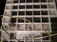
moray james,I have thought most all those issues before I before built them.
As these were the first ones I had built I only used two forms of connecting the stators and wasn't sure what the voltage levels were going to be at the time (thinking +10kv or more).
So being in a hurry I didn't elaborate on a very good connection system but I am going to do something much better on the next ones very soon.
Nickel print works very good for the boken off powder coated aluminium connecetions as they get brittle and break off.
my design doesn't require any special glues.
I checked the all the wires continuity with a beeper and found no issues there.
I sealed all the edges with G.E CLEAR SILICONE all the way around, but this can get messy, so much care must be taken.
I originaly used super glue to glue the screens ,but on p.c.a ones , again was in a hurry and I used a monokote iron to seal the glue faster and damaged the coating in a couple of spots but they still worked and those were corrected in the rebuilding of them.
The oxide issue?
Well,I just scrubbed them down with some steel wool and the powder coater used what ever treatment they use.
I think washing them with a weak solution of lye should sufice.
Which brings me to primer?
An etching type zinc chromate type I have in mind for two reasons,
#1 to provide the smoothest posible surface for any of top coats eliminating any air bubbles and adding flexiablity at the wire joints and adding adhesion to the topcaoat (the reason primer is used in the first place) avoiding any cracks in the insulation.
#2 being that it has zinc in it probaly have some sort of a high resistance this could help with charge migration on the stators in theory possibly lowering distortion.
In the next build I am considering using a polyurethane glue as opposed to only super glue.
Through seven years of abuse the super glue seemed to get very brittle and didn't hold up in a few spots.
If I reglue with poly glue, Not only will it be stonger and last longer, it will be cheaper compared to just using super glue.
Poly glue is thicker and may even eliminate the need for the messy silicone rubber. jer
Attachments
- Home
- Loudspeakers
- Planars & Exotics
- ESL Diaphragm coating