I've been enjoying my DIY ESLs for several months now, but wanted to try a new ESL with a different purpose. Rather than doing a large panel I'd like to try something on a smaller scale.
For now there will only be one panel, a test mule to explore different construction techniques. A panel to answer some questions of mine and some others from the forum:
Can a smaller ESL produce acceptable volume levels?
Does a smaller curved panel help dispersion?
How do I tension a curved diaphragm?
Can the back wave be contained and still give good sound?
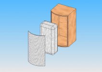
Here's an exploded view of the first concept. A curved stator with a wad of absorbent material and an 8" wide x 14-1/2" tall enclosure with 6" deep sides.
For now there will only be one panel, a test mule to explore different construction techniques. A panel to answer some questions of mine and some others from the forum:
Can a smaller ESL produce acceptable volume levels?
Does a smaller curved panel help dispersion?
How do I tension a curved diaphragm?
Can the back wave be contained and still give good sound?
Here's an exploded view of the first concept. A curved stator with a wad of absorbent material and an 8" wide x 14-1/2" tall enclosure with 6" deep sides.
Attachments
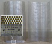
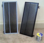
Here's a photo of the stators. 7-1/2" wide, 14" tall, and a 5-1/2 radius roll.
They're 0.032" thick aluminum with 0.125" dia. x 0.156 staggered holes, about 50% open area. One of the things I learned from the first build was to cut the edges to minimize sharp points to keep down leakage. The stators were rough cut 1/4" oversize on all sides, patterned matched, and screwed together before cutting both at once to final size.
I made no attempt this time to smooth the burrs from punching and just rolled them with the best sides facing in.
Attachments
I'm going to try double sided tape to hold everything together. My first thought is 0.020" thick, 1/2" wide 3M VHB.
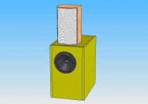
Here's a rendering of a curved ESL on top of my woofers. That's all for now, I need to do some thinking about how to tension the diaphragm, how to connect the electricals, how far apart and where to put diaphragm supports, how to make a curved grille, where to run the wiring, and the list goes on
Here's a rendering of a curved ESL on top of my woofers. That's all for now, I need to do some thinking about how to tension the diaphragm, how to connect the electricals, how far apart and where to put diaphragm supports, how to make a curved grille, where to run the wiring, and the list goes on
Attachments
Thanks for the updates, BillH. I'll be interested to hear what you discover. My attempts quite awhile ago to use thin aluminum and 0.032" tape led to quite a few diaphragm/stator contact problems, but I was working with longer stators. Perhaps your more compact design will make it easier to maintain the gap.
Few
Few
Andy, while I can't help you identify them, they do look familiar. Have you tried to listen to them?
Few, the spacer configuration seems like the secret to keeping the diaphragm away from the stator. I'm considering four possibilities at the moment, shown below. Right now #2 and #4 look like the best way to maintain the curvature of the diaphragm. I like the idea of #4 to break up the resonances, but not sure if it would make any difference. In all cases the narrow dimension of the rectangular sections or largest dimension of the tapered sections is about 2", appropriate for a 0.020" spacer thickness.
Have you tried to listen to them?Few, the spacer configuration seems like the secret to keeping the diaphragm away from the stator. I'm considering four possibilities at the moment, shown below. Right now #2 and #4 look like the best way to maintain the curvature of the diaphragm. I like the idea of #4 to break up the resonances, but not sure if it would make any difference. In all cases the narrow dimension of the rectangular sections or largest dimension of the tapered sections is about 2", appropriate for a 0.020" spacer thickness.
Attachments
BillH said:Andy, while I can't help you identify them, they do look familiar.
Yes. As good as my old QUADs ! (at least in the top end
)Andy
BillH,
I agree that your numbers 2 and 4 look the most promising. I wouldn't expect the vertical spacers in #1 and #3 to ensure a curved diaphragm. Doesn't the diaphragm curve have to match the stator curve, or am I confused about what you're doing?
Also, I should clarify what I meant in my previous post. When I made prototypes with the 0.032" thick spacers I followed the usual rule of thumb:
(spacer separation) < or = 100 x (diaphragm/stator gap)
(did I remember that correctly? it's been awhile...) In any case, the problem I encountered was that I could never completely avoid minor bends or kinks in the thin aluminum stator material. Those kinks didn't cause trouble with a 1/16" gap, but they caused major headaches with the 1/32" gap because there was so little room for error.
Don't get me wrong I'm certainly not trying to convince you to change your plans. I just didn't want to see your posts go unacknowledged and thought I'd toss in a description of my previous experience in case it was useful. In fact, I'm in the process of accumulating the materials for some panels with 0.040" (1 mm) gaps in spite of the trouble I described above. I'm going to use tensioned wire in the hope that I'll be able to keep things flatter.
Few
Hi,
Q and A
Q1: Yes, but only at elevated frequencies
Q2: Yes, curving broadens dispersion, but not much
Q3: Only in the ´straight´ direction and best is imo with high tension
Q4: Yes, but You´ll probabely need a very deep and voluminous housing to eliminate back sound completely.
Using sheet metal You should keep in mind, that the edges of the sheets are the most probable points where flashovers occur.
My assumption is that cutting both sheets at once will be a nearly perfect provedure of creating a sparking stator!
I did the cutting separately for every sheet. The reason is as follows:
If You look at the pic You might notice that the rim is cut in a way that no sharp points are left. Since You can´t avoid the stamp like rim with usual hole patterns You should ensure that the sheet is cut in a way that the ´leftover holes´ at the rim are less than 50% their original area. More than 50% left and there will be very sharp pinpoints and sparking. This will work when You cut each sheet individually. Small tolerances in overall dimensions are acceptable, whereas early sparking renders the panel useless.
Secondly I used a good thick insulation of ~0.5mm thickness.
Thirdly I glued some clear thin tape around the rim, thereby assisting the insulation. Beeing of PVC or PP-material this is good for several 100V of stable insulation on its own.
With curved stators (curved in the horizontal plane only!) I´d suggest only the spacer pattern No.2
You might think of varying the distance between adjacent spacers a bit as ML did. Theoretically this should broaden the ground resonance peak and minimize it´s Q-factor, but in praxis I found no difference to a equidistanced spacer-stator. The rule of thumb of placing the spacers is 70:1...100:1 times the d/s depending on the mechanical tension You´ll use (higher tensioning force allows for higher ratio). Don´t go smaller, because of efficiency reasons and don´t go higher because of dynamical stability reasons.
Patterns like No.4 don´t avoid resonance problems but reduce efficiency because of a higher shunt capacitance.
Shunt capacitance is already the highest with simple sheet metal stators and is higher the smaller the panel ´s area becomes.
Large and curved stators are in advantage against flat ones because You only need a lot of glue joint area in the (straight) direction of membrane tension (top and bottom rim). The width of the glue joint along the long sides can be considerably smaller since it takes no shearing stress.
As Few already said will it be difficult to create a perfectly flat or perfectly equally curved stator with sheet metal. As a result there is a lowest spacer thickness down to which the warps of the sheet don´t play such an important role. This seems to be ~1mm (0.04"). If You intend to manufacture smaller gaps You should have certain experience especially with curved designs and have prime material to start with.
The soft tapes of 3M -I like to use them very much, because of the ease of usage and their damping characteristics- underly tolerances of their own which are bigger than for e.g hard plastics. I assume this discloses them for gaps smaller than 1mm (best usage is ~1.5mm).
3M offers a VHB-tape thats specially intended for use with powdercoated surfaces. The 495x- and 595x-series are promising as glue joint and the 491x-series as clear spacers. You might think of using round or rectangle shaped silicon bands as horizontally orientated membrane spacers too.
When You use these tapes You should always be aware that You have just one shot to get the membrane precisely where You want it! You can´t correct for failures -like wrinkles- by heating the membrane after montage.
On the other hand montage becomes quite easy and quick, which is important since the glue joints of the membrane in the tensioning frame are stressed with high shearing forces.
So far so good
jauu
Calvin
Q and A
Q1: Yes, but only at elevated frequencies
Q2: Yes, curving broadens dispersion, but not much
Q3: Only in the ´straight´ direction and best is imo with high tension
Q4: Yes, but You´ll probabely need a very deep and voluminous housing to eliminate back sound completely.
Using sheet metal You should keep in mind, that the edges of the sheets are the most probable points where flashovers occur.
My assumption is that cutting both sheets at once will be a nearly perfect provedure of creating a sparking stator!
I did the cutting separately for every sheet. The reason is as follows:
If You look at the pic You might notice that the rim is cut in a way that no sharp points are left. Since You can´t avoid the stamp like rim with usual hole patterns You should ensure that the sheet is cut in a way that the ´leftover holes´ at the rim are less than 50% their original area. More than 50% left and there will be very sharp pinpoints and sparking. This will work when You cut each sheet individually. Small tolerances in overall dimensions are acceptable, whereas early sparking renders the panel useless.
Secondly I used a good thick insulation of ~0.5mm thickness.
Thirdly I glued some clear thin tape around the rim, thereby assisting the insulation. Beeing of PVC or PP-material this is good for several 100V of stable insulation on its own.
An externally hosted image should be here but it was not working when we last tested it.
With curved stators (curved in the horizontal plane only!) I´d suggest only the spacer pattern No.2
You might think of varying the distance between adjacent spacers a bit as ML did. Theoretically this should broaden the ground resonance peak and minimize it´s Q-factor, but in praxis I found no difference to a equidistanced spacer-stator. The rule of thumb of placing the spacers is 70:1...100:1 times the d/s depending on the mechanical tension You´ll use (higher tensioning force allows for higher ratio). Don´t go smaller, because of efficiency reasons and don´t go higher because of dynamical stability reasons.
Patterns like No.4 don´t avoid resonance problems but reduce efficiency because of a higher shunt capacitance.
Shunt capacitance is already the highest with simple sheet metal stators and is higher the smaller the panel ´s area becomes.
Large and curved stators are in advantage against flat ones because You only need a lot of glue joint area in the (straight) direction of membrane tension (top and bottom rim). The width of the glue joint along the long sides can be considerably smaller since it takes no shearing stress.
As Few already said will it be difficult to create a perfectly flat or perfectly equally curved stator with sheet metal. As a result there is a lowest spacer thickness down to which the warps of the sheet don´t play such an important role. This seems to be ~1mm (0.04"). If You intend to manufacture smaller gaps You should have certain experience especially with curved designs and have prime material to start with.
The soft tapes of 3M -I like to use them very much, because of the ease of usage and their damping characteristics- underly tolerances of their own which are bigger than for e.g hard plastics. I assume this discloses them for gaps smaller than 1mm (best usage is ~1.5mm).
3M offers a VHB-tape thats specially intended for use with powdercoated surfaces. The 495x- and 595x-series are promising as glue joint and the 491x-series as clear spacers. You might think of using round or rectangle shaped silicon bands as horizontally orientated membrane spacers too.
When You use these tapes You should always be aware that You have just one shot to get the membrane precisely where You want it! You can´t correct for failures -like wrinkles- by heating the membrane after montage.
On the other hand montage becomes quite easy and quick, which is important since the glue joints of the membrane in the tensioning frame are stressed with high shearing forces.
So far so good
jauu
Calvin
Hi, Few.

Hi, Calvin.
So the plan has changed, as it sometimes does. Curved stators are out and flat is in. I'm thinking of going with the same 7-1/2" x 14" finished size and using flat steel stators instead of aluminum for the extra stiffness. I liked the VHB tape, but on a small ESL like this it covers a relatively large surface area. I'm considering going back to stacked acrylic insulators with a small cross section.
I've put down the tools and taken a break to think about this for a day or two. The goal is to produce a small ESL hybrid that can be integrated with a woofer and used as close to the wall as possible. Ear splitting volume is not needed.
Today's question:
Should I split the panel into midrange and tweeter sections?
I did it on my last ESLs, but they suffer from a 'phasing' (lobing?) effect as I move left to right. A single section would be much easier to build, but the promise of a narrow tweeter section spreading the highs is tempting.
Yes, it does have to curve. More on that later.Few writes: Doesn't the diaphragm curve have to match the stator curve
That's the rule of thumb I've been using, too.Few writes: (spacer separation) < or = 100 x (diaphragm/stator gap) (did I remember that correctly? it's been awhile...)
I've got that problem, too. Dropping them makes it worse, as I found out yesterday.Few writes: In any case, the problem I encountered was that I could never completely avoid minor bends or kinks in the thin aluminum stator material.
I appreciate all the help I can get, thanks for the advice.Few writes: I just didn't want to see your posts go unacknowledged and thought I'd toss in a description of my previous experience in case it was useful.
Hi, Calvin.
I did it this way to make sure the patterns matched on both stators. My first build ended up with some stator pairs that had openings that didn't match front to back. I don't know if it matters, but this time I wanted them to match. After shearing to final size, I spent some time with a file and sandpaper to get rid of burrs.Calvin writes: My assumption is that cutting both sheets at once will be a nearly perfect provedure of creating a sparking stator!
Yes, as I found out first hand. I've abandoned the curved stators after trying to mount the diaphragm. The diaphragm tension is critical on a curved ESL. Too much tension and it pulls in between the spacers-ruining the diaphragm to stator distance, too little tension and the diaphragm is wrinkled. There's just not enough room for error.Calvin writes: If You intend to manufacture smaller gaps You should have certain experience especially with curved designs and have prime material to start with.
So the plan has changed, as it sometimes does. Curved stators are out and flat is in. I'm thinking of going with the same 7-1/2" x 14" finished size and using flat steel stators instead of aluminum for the extra stiffness. I liked the VHB tape, but on a small ESL like this it covers a relatively large surface area. I'm considering going back to stacked acrylic insulators with a small cross section.
I've put down the tools and taken a break to think about this for a day or two. The goal is to produce a small ESL hybrid that can be integrated with a woofer and used as close to the wall as possible. Ear splitting volume is not needed.
Today's question:
Should I split the panel into midrange and tweeter sections?
I did it on my last ESLs, but they suffer from a 'phasing' (lobing?) effect as I move left to right. A single section would be much easier to build, but the promise of a narrow tweeter section spreading the highs is tempting.
Can you figure out what the source of the lobing is in your current panels? That might help you decide whether to repeat that configuration. I'd also be interested to hear what you find.
If you only run the narrow tweeter strip, and disable the wider panels, is lobing still evident? If so, and the tweeter panel is quite narrow, then maybe diffraction or reflections from the support structure are to blame.
If lobing shows up when only the midrange panels are used then that would seem to suggest that the midrange needs to be rolled off at a lower frequency. Unfortunately, that might put too much strain on your tweeter.
If both the tweeter and midrange panels need to be running in order for lobing to be evident then interference between the two panels may be the culprit. Steeper filters to limit the range over which both panels contribute might solve the problem. Of course steeper filters aren't as easy to install as a single resistor in series with the midrange panel.
Hi,
"The diaphragm tension is critical on a curved ESL. Too much tension and it pulls in between the spacers-ruining the diaphragm to stator distance, too little tension and the diaphragm is wrinkled. There's just not enough room for error."
Actually its not that bad
Important is that You apply lots of tension in the straight direction and just enough tension in the curved direction to straighten out wrinkles ...thats all! It helps in the beginning to have a tensioning frame that is considerably longer than the panel and just to use the middle part of the diaphragm.
jauu
Calvin
Calvin writes: It helps in the beginning to have a tensioning frame that is considerably longer than the panel and just to use the middle part of the diaphragm.
Hi, Calvin. My DIY stretching frame wasn't very effective. It was a collection of pine lumber, threaded rod, wood dowels, and double sided tape. I needed something like this jig from Shackman.de.
Hi, Few. Thanks for all the advice. I'm going to use the electronics from one of my current ESLs for this project and will be able to try out your ideas when I start testing. I'll let you know what happens.
Here's a picture of the latest version of the stators with a 500 gm roll of solder next to them for scale. It's going to be a simple flat panel built from 0.050" thick aluminum with 0.057 diameter holes, 35% open area and a 4-1/4" x 11-1/4" actual radiating area. The non-staggered hole pattern made cutting an edge with no sharp edges very easy.
The insulators are 0.025" thick acrylic sheet super glued to the stators with a divider that breaks up the diaphragm into 2-1/2" and 1-3/4" wide sections. The VHB tape from the first version didn't work out very well. It needed it to cover more area than I was willing to give it to be effective. I've used VHB in real life and it can perform extremely well when used correctly. My first try just wasn't a good usage of it.
I tried a couple of things that seemed like a good idea at the time. Each stator has an short edge bent at 90 degrees to the face to give it some rigidity and I added four legs for mounting. Each of the holes in the legs will have a rubber grommet added later. The legs should also make a good connection point for wires.
Attachments
Hi, R. A small ESL is built exactly the same as a large one. Have a look at ESL Projects at The Audio Circuit for a collection of ESL builds.
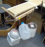
Stretching and attaching the diaphragm went without incident. The picture below shows my stretching jig. It's a piece of 3/4" MDF with a 6 micron Hostaphan diaphragm taped to the top on two sides. The free edges have wood strips clamped on and weights to give tension to the film. I gave it just enough weight to take out the wrinkles. After it was glued to the insulator, I had to use a hair dryer to get out a few small wrinkles.
I'm working on a new diaphragm coating, a glue based DIY formula that is a variation of the one used on my first ESL. A test film is coated and I want to check it tomorrow to see if it still measures OK. If it works I'll be able to put the small ESL together and try it out this weekend.
Attachments
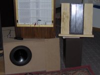
The small ESL is up and running and it sounds great. It has a very similar sound to my larger ESLs with less low end as would be expected from a smaller panel. The small ESL seems to be about as efficient as the larger panels, but plays louder. The smaller capacitance lets my amplifier deliver more power before its protection circuit kicks in.
The highs are crisp and extended, just how I like it. With a 12db/octave @100Hz crossover I can drive the diaphragm into the stators at loud volumes, but a 12db/octave @200Hz crossover cures that. My first guess at a good crossover point would be in the range of 1Khz to 2KHz. Without some help from a woofer in the lower midrange, male voices sound a bit thin. High frequency dispersion is still limited both vertically and horizontally, but that's not a huge problem for me.
The picture shows the small ESL on the right, large ESL in the center, and an 8" woofer on the right. The large ESLs are providing bias voltage and the audio step-up transformer.
Attachments
Here's a screenshot of the small ESL without equalization. The microphone is 3" away from the center of the ESL and white noise is being fed to the ESL. The high end of the graph looks a lot like my larger ESL with a broad rise at 6Khz and a dip above 10KHz.
Attachments
BillH-
Thanks for the updates. I'm surprised to hear that "The small ESL seems to be about as efficient as the larger panels, but plays louder." Can you remind me what the spacing and overall size are for the large panels? I'm assuming the small one keeps up with the large one because of a significantly smaller stator/diaphragm gap, but I'm still surprised the maximum loudness of the small one is greater. Is your amp's circuitry limiting the loudness of the large panels at fairly low SPLs?
Few
Hi, Few. Me, too. Even though I was careful and checked my work, part of me was surprised it worked at all.Few writes:I'm surprised to hear that "The small ESL seems to be about as efficient as the larger panels, but plays louder."
This happened with a reduced bias voltage, too. When I first started the small ESL I forgot to turn down the bias voltage. It sounded like bacon frying. When I turned it off, I could hear the diaphragm that had stuck to the stator slowly deattaching itself. Fortunately there was no permanent damage.About 0.060" diaphragm to stator spacing and about 3 square feet of radiating area.Can you remind me what the spacing and overall size are for the large panels?
I believe it is. The amp is nothing special, a Kenwood 100 watt x 4 home theater receiver. I am grateful for the protection circuit. Without it I would have left the magic smoke out of the amplifier several times.Is your amp's circuitry limiting the loudness of the large panels at fairly low SPLs?
I think the next step will be to make a new pair of small panels based on this one complete with bias supplies and step-up transformers so I can move on to enclosing the back wave. Has anyone tried the cheap CCFL power supplies for bias? I'd like to try to avoid building them from scratch if possible. I'm also looking for cheap toroids to try as audio transformers.
- Status
- This old topic is closed. If you want to reopen this topic, contact a moderator using the "Report Post" button.
- Home
- Loudspeakers
- Planars & Exotics
- An ESL Experiment