There is perhaps the possibility of using active carbon, but the exhaust must then also removed and blown through,
other companies have the electrode in a quartz part and then claim that it would no longer smell, which I do not believe.
Thus, the German company Lantsche which produces the Corona. The claim that their cell quartz the Ozone completely destroyed.
Lantsche
But this explanation can be found only in the German part of the page
Then the exhaust converted into other compounds, who can guarantee that not even smell or toxic?
Like a catalyst in the car, as is also still poison and stench out.
And louder is not guaranteed
Regards,
George
line level will drive one, remember the device is an Amplifier and a radio transmitter in one. Standard dB/W/m efficiency numbers are meaningless here.
To do a comparison against a conventional tweeter you would measure the power consumption of the amplifier driving the tweeter.
That would be different depending on the efficiency of the tweeter, the class of the amplifier and so on.
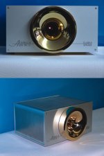
the one in the pictures I posted was drawing about 125mA from a 700Vdc power supply.
the input signal to the modulator was 200mW, we were measuring somewhere between 93 and 98 dB(A) at 1m but the meter was being affected by the radio radiation so I don't trust it.
It was loud enough to be uncomfortable to be near. We were outside and a 10kHz tone could be heard inside the house over the air conditioner noise in the kitchen behind a brick wall, several internal walls and closed doors.
We were driving it with a 200mW MP3 player. It was unshielded and we were pumping out about 100 watts of radio energy, we didn't want to risk any valuable equipment on the test setup. It has already damaged a power supply on a scanner.
You could use the output of your SET and reduce the gain of the modulator.
To do a comparison against a conventional tweeter you would measure the power consumption of the amplifier driving the tweeter.
That would be different depending on the efficiency of the tweeter, the class of the amplifier and so on.
the one in the pictures I posted was drawing about 125mA from a 700Vdc power supply.
the input signal to the modulator was 200mW, we were measuring somewhere between 93 and 98 dB(A) at 1m but the meter was being affected by the radio radiation so I don't trust it.
It was loud enough to be uncomfortable to be near. We were outside and a 10kHz tone could be heard inside the house over the air conditioner noise in the kitchen behind a brick wall, several internal walls and closed doors.
We were driving it with a 200mW MP3 player. It was unshielded and we were pumping out about 100 watts of radio energy, we didn't want to risk any valuable equipment on the test setup. It has already damaged a power supply on a scanner.
You could use the output of your SET and reduce the gain of the modulator.
George Green said:There is perhaps the possibility of using active carbon, but the exhaust must then also removed and blown through,
other companies have the electrode in a quartz part and then claim that it would no longer smell, which I do not believe.
Thus, the German company Lantsche which produces the Corona. The claim that their cell quartz the Ozone completely destroyed.
Lantsche
But this explanation can be found only in the German part of the page
Then the exhaust converted into other compounds, who can guarantee that not even smell or toxic?
Like a catalyst in the car, as is also still poison and stench out.
And louder is not guaranteed
Regards,
George
I think ozone will oxidise the carbon to CO2 (or maybe CO), so a carbon catalyst will wear out quite fast.
Silver black is the standard way of removing ozone; the byproduct is pure oxygen, so there shouldn't be a smell. Silver slowly oxidises, but the oxide (which is itself a metal, although black) is still an effective catalyst, although somewhat less active than the pure metal.
lumanauw said:Hi, George,
Is this tweeter has the same operating principle with Acapella ion tweeter?
yes.
the Acapella is essentially an upgraded Ionovac...
_-_-bear
PLEASE PLACE A FULL COVERAGE GROUNDED SCREEN AROUND ANY PLASMA TWEETER!!
This includes the coil and tube... anything that has RF on it.
You need a screen with relatively small holes - metal window screen should work ok.
Otherwise you have a relatively high power transmitter, operating illegally - and potentially interfering with broadcasts and various services!!
A portable shortwave receiver will tell you how you are doing in that department.
_-_-bear
Hi George, I'm not trying to threadjack or anything, but I'm at my wit's end trying to get my plasma tweeter to work and since your email seems to be disabled I figured I should ask my question here. What I'm trying to do is make essentially the same circuit that everyone does with a screen driven pentode, but then use an 811A linear amplifier to get more power. I have a schematic that is located at this link.
http://www.flickr.com/photos/14031769@N06/1896939128/sizes/l/
anyone please feel free to comment on it, whether it is even possible or not to do what I'm trying to do.
Thank you.
http://www.flickr.com/photos/14031769@N06/1896939128/sizes/l/
anyone please feel free to comment on it, whether it is even possible or not to do what I'm trying to do.
Thank you.
Impedance mismatch between the two stages?
you need to show the output inductor as well. and probably take your positive feedback from the final output. the frequency changes as it starts up for better drive, this is intentionbal, because the load changes as the arc flame builds. think of it as self tuning for max power by changing freq.
you need to show the output inductor as well. and probably take your positive feedback from the final output. the frequency changes as it starts up for better drive, this is intentionbal, because the load changes as the arc flame builds. think of it as self tuning for max power by changing freq.
angsuman said:Hi George, I'm not trying to threadjack or anything, but I'm at my wit's end trying to get my plasma tweeter to work and since your email seems to be disabled I figured I should ask my question here. What I'm trying to do is make essentially the same circuit that everyone does with a screen driven pentode, but then use an 811A linear amplifier to get more power. I have a schematic that is located at this link.
http://www.flickr.com/photos/14031769@N06/1896939128/sizes/l/
anyone please feel free to comment on it, whether it is even possible or not to do what I'm trying to do.
Thank you.
Ok, if ur going to mess around with relatively high power tubes, you should know what you are doing first.
There are several errors in your schematic.
I'm more concerned about the high power level you will have there, IF it works - if you do not thoroughly shield this device, you will be making SERIOUS levels of RFI. In the USA, you'll be operating a radio transmitter without a license, and liable for some serious penalties if some local ham hears you and finds you, tells the FCC... Be sure to be extra special careful to DOUBLE shield everything.
YOU CAN NOT MAKE IT LOOK PRETTY by having those nice tubes glowing on top of a chassis!! IT HAS TO BE SHIELDED FULLY!!
[beats horse to death...]
Also keep your hands OUT of the thing once it is wired up.
The 1200vdc is DEADLY!!
RF burns hurt a whole lot too...
EXCERCISE EXTREME CAUTION!!
Yes I understand the dangers involved and we're doing this under the supervision our physics teacher who has much experience around high voltages and we do shield the whole structure with a faraday cage.
Yes the 100uH chokes are an error from an older schematic really its a simple bifilar wound choke we wound on a ferrite core and about 12 turns of wire.
I have added an impedance PI matching circuit between the 807 and the 811A tubes.
OzMikeH: What do you mean I have to show the output inductor as well?
I thought I was taking positive feedback from the final output at the hot end of the Tesla coil?
Serge: I thought I would need the two 0.1uf capacitors across the heaters to keep the AC filament hum out of the signal?
Thank you everyone for your responses.
This is ONLY needed in RF-powered plasma, and you really shouldn't be putting RF near your audio. DC is the way to go, and has historically produced the best results.bear said:PLEASE PLACE A FULL COVERAGE GROUNDED SCREEN AROUND ANY PLASMA TWEETER!!
abzug said:
This is ONLY needed in RF-powered plasma, and you really shouldn't be putting RF near your audio. DC is the way to go, and has historically produced the best results.
Ummm... do tell??
What commercial "DC" plasma speakers are there?
All of the famous ones I know of are "RF" type - the Ionovac and Ionofane being the most famous back in the 50's...
All of the commercial plasma speakers, like the Acappella, today are well shieded, look at the enclosures?
The only DC based HV plasma speaker I know of was Gerald Shirley's "Corona Wind Loudspeaker" from the JAES in the 50's...
_-_-bear
angsuman said:Yes I understand the dangers involved and we're doing this under the supervision our physics teacher who has much experience around high voltages and we do shield the whole structure with a faraday cage.
I'm still concerned, did the physics teacher "approve" the schematic?? If so, I'd not have much confidence in his knowledge of HV & RF circuits...
Since you do NOT need such power to make a working plasma tweeter - as shown here by George - why then are you trying to pump up the power levels??
Yes the 100uH chokes are an error from an older schematic really its a simple bifilar wound choke we wound on a ferrite core and about 12 turns of wire.
I have added an impedance PI matching circuit between the 807 and the 811A tubes.
What is the impedance at the cathode of the two 811As?
Can you measure it?
Calculate it?
How do you know that it is what it calculates out to be?
[OzMikeH: What do you mean I have to show the output inductor as well?
I thought I was taking positive feedback from the final output at the hot end of the Tesla coil?
Serge: I thought I would need the two 0.1uf capacitors across the heaters to keep the AC filament hum out of the signal?
Think about it some more... what type of amplifier is that?
")
How does it work?
And how much drive do 811As require in this configuration?
You should have an ARRL Handbook and a W6SAI Bill Orr "West Coast Handbook" at your side for this...
Thank you everyone for your responses.
One of the keys do doing design is asking good questions, and then finding the answers...
_-_-bear
PS. I have emphasized the need for shielding and a good faraday cage because this is a DIY forum, and this little detail might not be otherwise noticed or even known by many...
Yeah I understand, I'm here to learn. It's essentially in the design phases, my physics teacher does not have much knowledge of circuits because he's a mechanical engineer by trade. However I did get the schematic approved of, or at least showed to Max Robinson, at www.funwithtubes.com. He told me that the input impedance of 811A tubes at the cathode was about 200 ohms. And I designed a PI matching circuit with that knowledge. He also recommended an ARRL handbook which I'll probably look into. The reason why I want more power into it is to try to lower the cut-off frequency. I'll go learn more about radio frequency amplifiers, I already have much experience with audio amplifiers and loudspeakers but I guess I have lots to learn about radio.
- Status
- This old topic is closed. If you want to reopen this topic, contact a moderator using the "Report Post" button.
- Home
- Loudspeakers
- Planars & Exotics
- Plasmatweeter