Now I think it's time to clear some physical facts before You give unqualified tips to people.
There are significant properties that makes neo magnets much better.
One of them (and that is the major) is that You WILL get higher efficiency from the speaker using them
The plain physical fact is that they have MUCH higher magnetic flux then ferro magnets.
Jamesbos... You really need to rethink Your magnetic layout on Your speakers as You do it ALL WRONG with magnetic collapse as a result.
Cheers!
First of all, You should never ever put the opposite poles side by side so that they make contact.
That will ruin the whole design idea as the magnetic flux will direct itself immediately to the magnet touching next to it.
So N should NEVER EVER touch the S on the same plane.
Cheers!
That will ruin the whole design idea as the magnetic flux will direct itself immediately to the magnet touching next to it.
So N should NEVER EVER touch the S on the same plane.
Cheers!
Good point. Several people have suggested that a gap should be left between the columns of magnets. I think they had other reasons, ie either to leave area for air to move or because it would enable the use of fewer magnets.
But it seems reasonable to believe that if the N and S were touching, the field would almost act like there was a short, there, and not as much would extend out to the mylar.
So that leads me to believe that for a particular distance to the mylar, there should be an optimal spacing for the N and S columns, that would maximize the field stength in the plane of the mylar, where the foil is.
Last edited:
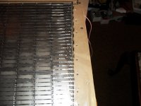
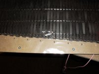
yeah always leave space in between the North and South poles, this is where ur foil runs on the mylar, this is the reason why magnepan uses allot of rows of small magnet strips in the lenght of the speaker so you can run allot of foil or wire in the gaps. this layout is not verry usefull when you have big magnets, take another look at the epsilon layout everywhere the foil should run there must be a gap between 2 magnets atracting one another, but dont let them touch eachother. the closer together the higher the fields strength. remember that the sound needs to go out of the speaker to so dont go smaller then gap of 1 mm (and be sure there are holes in the metal in this gap or the sound just bounces against it instead of going into ur room). for instance if you put an esl against the wall all ur low end and allot of the Sensitivity will be gone!
So the gap is importend for 2 reasons.
Try to create a layout where you get the most length of gap out of ur magnets, so you can use as much coil so ur mylar is driven as uniform as possibble.
arange magnets like NORTH SOUTH NORTH SOUTH NORTH SOUTH ETC between north and south you let the foil run up the speaker and with south north back down again just repeat it.
dont mess that up or some of ur foil will be playing out of phase canceling the other sound so you wil end up with nothing, or far less.
Last edited:
I have to rebuild all my neo speakers as well, now I am using 3 mm wide tape, more pain for the old back. I know neos are stronger than ferrites, I have the blood blisters to prove it!! After building over 60 full range planars of all sizes and layouts I think I know what I am doing by now. The secret to sensitivity is using all the magnet area you can. Which I aim to do with all my re-re-builds. I am confident I will increase sensitivity quite significantly with the same number of magnets. I did build one with gaps between the magnets, but gave up the idea, as the magnets were unstable even with super glue, and there wasn't any improvement in sensitivity, worth the extra work involved. As I said the 60 x 40 using ferrites is 8 Db more sensitive than the large 4' x 2' one using neos, which I already know are much stronger. The important difference is in the foil layout. The opposite is true when you just use the normal layout of putting the foil over the intersection of the N & S. If this makes me unqualified so be it!!
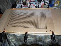
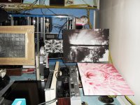
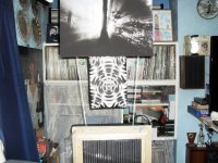
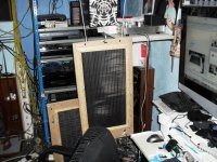
some more reduced pictures
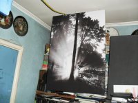
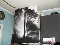
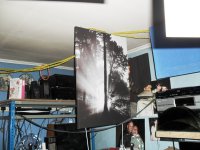
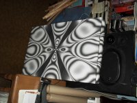
some more pictures with new covers, canvases quite cheap.
some more pictures with new covers, canvases quite cheap.
Attachments
-
 SAM_0485.JPG354.1 KB · Views: 379
 -
 SAM_0494.JPG462.5 KB · Views: 85
 -
 SAM_0493.JPG415.3 KB · Views: 77
 -
 SAM_0492.JPG467.9 KB · Views: 77
 -
 SAM_0491.JPG405.6 KB · Views: 78
 -
 SAM_0490.JPG375.7 KB · Views: 73
 -
 SAM_0489.JPG363.8 KB · Views: 330
 -
 SAM_0488.JPG386 KB · Views: 337
 -
 SAM_0487.JPG371.5 KB · Views: 344
 -
 SAM_0486.JPG357.9 KB · Views: 352
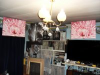
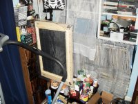
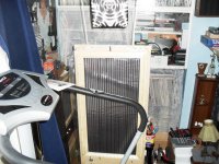
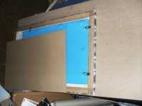
some more of the same
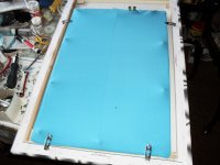
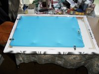
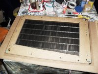
ditto,the blue material acts as a dust cover.!!
ditto,the blue material acts as a dust cover.!!
Attachments
-
 SAM_0504.JPG328.3 KB · Views: 97
 -
 SAM_0503.JPG350.5 KB · Views: 107
 -
 SAM_0502.JPG400.5 KB · Views: 102
 -
 SAM_0501.JPG458.6 KB · Views: 85
 -
 SAM_0500.JPG452 KB · Views: 105
 -
 SAM_0499.JPG465.1 KB · Views: 429
 -
 SAM_0498.JPG445.3 KB · Views: 444
 -
 SAM_0497.JPG354.6 KB · Views: 471
 -
 SAM_0496.JPG344.6 KB · Views: 491
 -
 SAM_0495.JPG419.2 KB · Views: 515
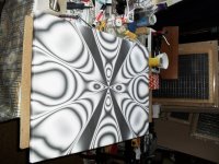
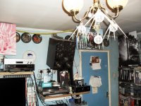
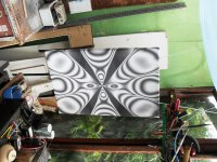
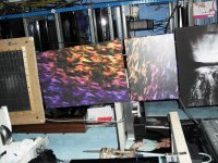
some more.
Still learning as I go along, very frustrating at times, especially when the same rebuild, does not have the same effect with a different speaker. magnets ,sizes, neos, ferrites you have to learn for each one by building it. Very time consuming, and can be very frustrating!!!£*)^%$
Still learning as I go along, very frustrating at times, especially when the same rebuild, does not have the same effect with a different speaker. magnets ,sizes, neos, ferrites you have to learn for each one by building it. Very time consuming, and can be very frustrating!!!£*)^%$
Attachments
-
 SAM_0511.JPG424.7 KB · Views: 65
 -
 SAM_0512.JPG414.5 KB · Views: 60
 -
 SAM_0513.JPG409.4 KB · Views: 50
 -
 SAM_0514.JPG354.1 KB · Views: 52
 -
 SAM_0510.JPG439.7 KB · Views: 72
 -
 SAM_0509.JPG434.1 KB · Views: 75
 -
 SAM_0508.JPG351.7 KB · Views: 62
 -
 SAM_0507.JPG474.7 KB · Views: 65
 -
 SAM_0506.JPG363.7 KB · Views: 72
 -
 SAM_0505.JPG369.4 KB · Views: 88
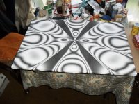
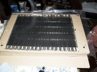
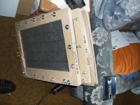
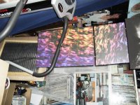
some more.
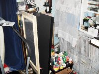
some more not finished yet a few more learned truths about full range planars to come next. As I have said I am still learning more as I go along.
some more not finished yet a few more learned truths about full range planars to come next. As I have said I am still learning more as I go along.
Attachments


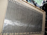
some updates.
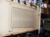
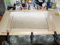
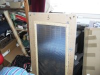
no. 1 & 2 are the same layout, using normal foil positioning. No. 2 uses a different type of plastic magnet same thickness and width. I had to cut the No. 2 plastic , by hand. It is 6 db more sensitive than No. 1
No. 3 is an improvement using the epsilon layout with an extra foil on the magnets, which are 3 mm thick neos. This was made possible by using the 3 mm tape instead of the 4.5 mm tape, I used previously. No. 4 is a 60 x 40 mm design using 6 mm thick neos, 12.7 mm wide. The original design was the normal layout, but with the new 3 mm tape, I reverted back to the epsilon layout, using the extra foil, which is a good improvement on the sensitivity. As I have said before the only way to improve things is to build the new layouts, it's the only way. All the new ones have to be built to compare with the old ones. It doesn't always work, but that is called progress. All the theorizing in the world cannot beat the actuality of building the dammed thing.
Attachments

I mostly disagree with both of you, on that one. One of the main reasons engineering exists is so we can KNOW if and how something is going to work, BEFORE we build it.
And that can definitely beat (even just on cost, alone) building lots of them that don't work well-enough.
Of course, engineers sometimes decide to build and test rather than just calculate, if they have calculated that it's the best way, in that particular case.
And that can definitely beat (even just on cost, alone) building lots of them that don't work well-enough.
Of course, engineers sometimes decide to build and test rather than just calculate, if they have calculated that it's the best way, in that particular case.
Last edited:
If you can calculate,you can if you can't calculate like me you have to build. Anyway there are so many different parameters some known and some not known, which makes it almost impossible to calculate. Unless of course you are a genius, which I am not. I would rather build different designs than try to work out something which is impossible with all the known and unknown parameters of each design, as there are too many unknown factors.Especially if you design off the top of your head like I do. You live and learn, hopefully most of the time, which is the fun part when it works to your satisfaction. Perhaps I am too easily satisfied in your eyes!!
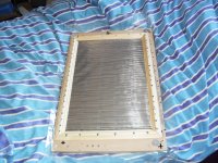
SOME MORE OF MY WORK, FINDING WHICH IS THE BEST DESIGN FOR DIFFERENTLAYOUTS AND SIZES
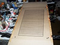
no. 1 Epsilon layout.
no. 2 Large one uses 6 mm ferrites 40 x 18 mm.
no. 3 Small one uses 50 x 12.7 x 3 mm neos.
no. 4 Blue one uses 50 x 12.7 x 3 mm neos.
no. 5 Uses 50 x 18 x 10 mm ferrites.
no. 6 Uses 25 x 6 x 2 mm neos. A4 size.
no. 7 & 8 Use 50 x 12.7 x 6 mm neos. These are being driven by SE Valve amp using EL 38 output tubes with 6J5GT input tubes and CV378 rectifier in my sun room. Plenty of sensitivity with the design using the epsilon layout with no gaps between the magnets.
Attachments

- Status
- This old topic is closed. If you want to reopen this topic, contact a moderator using the "Report Post" button.
- Home
- Loudspeakers
- Planars & Exotics
- Full range planar speaker using neo magnets