How do you build a frame for a wire stator type esl? I see pictures on the net and the stator/mylar almost goes right to the edge. Mine are going to be fullrange so it has to be really sturdy. I was thinking of making 2 frames out of 1,1/2" angle iron and sandwhitching everything in between them.
Also, is there any alternative to eggcrate? I want to show off my red magnet wire
Also, is there any alternative to eggcrate? I want to show off my red magnet wire
Hi,
You may wanna have a look here :
http://www.htforum.nl/yabbse/index.php?topic=47163.350
I am building 4 hybride ESL and I am describing the process with pictures.
It is in Dutch language, but the pictures may be useful
Geert
You may wanna have a look here :
http://www.htforum.nl/yabbse/index.php?topic=47163.350
I am building 4 hybride ESL and I am describing the process with pictures.
It is in Dutch language, but the pictures may be useful
Geert
Just an interesting thread:
http://www.diyaudio.com/forums/showthread.php?s=&threadid=88236&highlight=
http://www.diyaudio.com/forums/showthread.php?s=&threadid=88236&highlight=
gvy said:Hi,
You may wanna have a look here :
http://www.htforum.nl/yabbse/index.php?topic=47163.350
I am building 4 hybride ESL and I am describing the process with pictures.
It is in Dutch language, but the pictures may be useful
Geert
Those look nice! Are you haveing any trouble with warping wood?
v-bro said:Just an interesting thread:
http://www.diyaudio.com/forums/showthread.php?s=&threadid=88236&highlight=
I considered building them like that. I think even 3/4" ply would flex to much with 8'x3' fullrangers. They would need too much bracing.
Geert,
Those photos are very helpful. Thanks for providing the link. I obviously won't ask you to translate all the Dutch in that thread, but can you provide a few vital statistics? It looks like a great design. Here are the sorts of things I'm curious about. I don't want to burden you with too many questions so feel free to ignore any of them that you can't answer conveniently.
1) wire type and diameter (stranded or single conductor? PVC insulation? Conductor and insulation diameters?)
2) wires per cm?
3) size of opening in your frame (width and height?)
4) thickness of each wooden frame?
5) material used for the cross bars?
6) adhesive used to bond the wires to the cross bars?
7) distance between the diaphragm and one stator?
Also, I didn't see any photos showing the way the diaphragm is attached to the frame. Did you just make two spacers the same size as the frame and sandwich the mylar between them?
Thanks again for sharing your efforts.
Few
Few said:Geert,
Those photos are very helpful. Thanks for providing the link. I obviously won't ask you to translate all the Dutch in that thread, but can you provide a few vital statistics? It looks like a great design. Here are the sorts of things I'm curious about. I don't want to burden you with too many questions so feel free to ignore any of them that you can't answer conveniently.
1) wire type and diameter (stranded or single conductor? PVC insulation? Conductor and insulation diameters?)
2) wires per cm?
3) size of opening in your frame (width and height?)
4) thickness of each wooden frame?
5) material used for the cross bars?
6) adhesive used to bond the wires to the cross bars?
7) distance between the diaphragm and one stator?
Also, I didn't see any photos showing the way the diaphragm is attached to the frame. Did you just make two spacers the same size as the frame and sandwich the mylar between them?
Thanks again for sharing your efforts.
Few
Hi Few.
1. The wire is wire-wrap wire AWG24 (0.22mm²) single conductor with overall diameter of exactly 1mm.
2. I have 72 wires for aprox 16cm width.
Transparancy is 55%, ( 45% wire-55%open)
That means : wire (1mm)-open space (1.1mm)-wire(1mm) .......
3. panel size = 1240mm x 250mm
opening size = 1160mm x 170mm
4. Thickness= frame are made of standaard furniturepanel (pressed woodfibres with melaminetop) thickness 18mm.
5. crossbars are some sort of african hardwood ( 18mm*9mm)
(out of the diy marketstore)
6. I use TEC7 from novatech . This is some kind of gluekit.
You can see the tube on one of the foto's. I bring it on with a siliconepistol and even it with my fingertips. It is like silicone but it becomes harder and stronger like rubber after 24 hours.
7. I will have a spacing of 1mm.
The panels are made to work between 300Hz up to 20000Khz.
So the spacing must be minimal to ensure a good efficiency of the panel.
I am still constructing the panels , so I didnt fix the spacers and the membrane yet.
The spacer will be made out of 2mm thick neopreenrubber. I cut strips of 4cm width and glue them on the frame (round the edges)
After that I will strech the membrane on a stretchingtable and glue it on one of the stators .
After that I will coat the membrane with an airbrushpistol and a mixture of paperglue, water and airbrushpaint.
On the other stator I tape on the neoprenespacer around the frame a small copper tape ring to connect the membrane and I close the two spacers (so the copper tape contacts the coated membrane all around the edge to ensure a good loading of the membrane.
Geert
Hi,
so far Your project looks fine
I hope that Your wooden frame will work, since wood is a conductor for HV.
When You choose the neoprene, don´t choose black or grey...best is to use white.
Am I right that You glued the wires with the Tec7 after You mounted them in the frame? How do You assure the even distance to the membrane then?
How do You want to glue the membrane to the neoprene so that it lasts under mechanical tension?
Have You tested the coating already? There is an glue-formula without airbrush clour but using black ink instead, which I use for Years now and that works really well and can be applied by brushing (preferred) or airbrushing.
jauu
Calvin
Calvin said:Hi,
so far Your project looks fine
I hope that Your wooden frame will work, since wood is a conductor for HV.
When You choose the neoprene, don´t choose black or grey...best is to use white.
Am I right that You glued the wires with the Tec7 after You mounted them in the frame? How do You assure the even distance to the membrane then?
How do You want to glue the membrane to the neoprene so that it lasts under mechanical tension?
Have You tested the coating already? There is an glue-formula without airbrush clour but using black ink instead, which I use for Years now and that works really well and can be applied by brushing (preferred) or airbrushing.
jauu
Calvin
Hi Calvin.
I have build the similar way two ESL's before.
They are still playing for about 4 years now in my living room . It 'll work fine
Back then I used an MDF frame with hard wood crossbars. Now I use furniture panel with melamine finish and hardwood crossbars
The wires of the stator are isolated wires.
The wires are mounted under high tension in the frame.
They are really as flat as one can imagine while I am gluing them.
( same wires and same glue (tec7) as last time. Didnt have problems doing it this way.
Check the pictures, you see how I do it.
Gluing the membrane to the neoprene.
Now there you have a point. Last time I used double side tape extra strong.
It works but looses over the years a bit of its tension.
Now I ll try 2 component PU glue (may be)
I used it before to repair a Quad ESL63 with succes
It works well on the mylar and the ESL63 stator, but I am afraid It won't stick that well on neoprene.
May be I will choose the tape again. I will do some tests before.
The coating is made of velpon school glue.
A friend of me has for 5 years good working ESL's (I have made for him) and I still didnt have to recoat them.
Anyway I always construct the stators so that they can be opened easy incase I have to recoat.
Only when it is freezing outside and the air becomes very dry, I notice that it takes some time before they play at normal level.
I am however interested in your coating system.
greets
Geert
Hi,
I use some glue-formula too. I tried different ´more professional´ coatings, but apart from beeing much more expensive, I haven´t found one yet, that works clearly better. Still though there are some conductive polymeres that look very promising and I´ll try those out soon ;-)
Glueing again:
from the pictures I can´t see how You get a even surface of the TEC7.
As I understand You just run the glue over the wires where the crossbars are. So the material is right between the wires and the diaphragm. How do You even it out?
jauu
Calvin
Calvin,
First I put the stator in a bow form (a little of course), Then I run the wires .
Once all the wires are run, I release the stator and it springs back, pulling the wires completely flat.
The stator stays a bit in the bowform, because of the tension of the wires.
I gently press it flat to my working table and fix it .
Now the wires are really flat against the crossbars and under tension.
If I do a test with a straight profile placed on the stator wires, I can see it really is a flat wire plate I have.
Then I take the glue pistol with the tec7 .
I go over one crossbar and all the wires.
The Tec 7 is in the beginning the same as silicone (used in bathrooms )
So with 1 fingertip I can wipe it easily flat over all the wires.
The Tec 7 stays between the wires and it fixes on the crossbar and the wires. On the other hand it is wiped off almost completely above the wires. Of course there stays always a little, but that gives no real problems.
After 24 hours, the tec7 hardens out to a hard rubber substance (unlike silicone wich stays very flexible)
Now the wires are fixed to the crossbars and to each other.
There is no real tec7 substance under or above the wire. It is mostly between the wires and so attached to the crossbar.
Hard to explain, but infact an easy handling.
After I have loosen the stator (after 24 hours), It only stays in a very little bowform.
That is no problem, because the second stator has the same but of course opposite.
So when the 2 are fixed together (later on , ones the mylar is in place), The complete construction is straight.
Greets
Geert
gvy said:Calvin,
First I put the stator in a bow form (a little of course), Then I run the wires .
Once all the wires are run, I release the stator and it springs back, pulling the wires completely flat.
The stator stays a bit in the bowform, because of the tension of the wires.
I gently press it flat to my working table and fix it .
Now the wires are really flat against the crossbars and under tension.
If I do a test with a straight profile placed on the stator wires, I can see it really is a flat wire plate I have.
Then I take the glue pistol with the tec7 .
I go over one crossbar and all the wires.
The Tec 7 is in the beginning the same as silicone (used in bathrooms )
So with 1 fingertip I can wipe it easily flat over all the wires.
The Tec 7 stays between the wires and it fixes on the crossbar and the wires. On the other hand it is wiped off almost completely above the wires. Of course there stays always a little, but that gives no real problems.
After 24 hours, the tec7 hardens out to a hard rubber substance (unlike silicone wich stays very flexible)
Now the wires are fixed to the crossbars and to each other.
There is no real tec7 substance under or above the wire. It is mostly between the wires and so attached to the crossbar.
Hard to explain, but infact an easy handling.
After I have loosen the stator (after 24 hours), It only stays in a very little bowform.
That is no problem, because the second stator has the same but of course opposite.
So when the 2 are fixed together (later on , ones the mylar is in place), The complete construction is straight.
Greets
Geert
Could you discribe the glue formular that you use on the mylar?
Hi Badduh,
If you meen the glue formula for the coating?
It is VELPON Schoollijm (oplosmiddelvrij)
It is fully transparant and comes in a tube of100ml.
It is in fact a paperglue or hobbyglue.
I take 1 part VELPON, 3 parts water, some drops airbrushpaint (to color it) and I spray it with an airbrushpistol in several thin layers.
Geert
Gvy or V-bro. (or anybody elso how knows what trespa is )
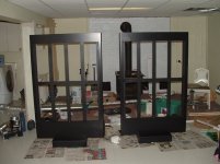
Do you think i could use Trespa (sorry don't know the english word for it). I thinking of sawing strokes of trespa and glue them with epoxy together. (see picture1)
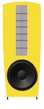
I don't want my frames to become to thick becouse i going to put them in a balfe where i also going to put the woofers in (see picture2)
pic1:
)Do you think i could use Trespa (sorry don't know the english word for it). I thinking of sawing strokes of trespa and glue them with epoxy together. (see picture1)
I don't want my frames to become to thick becouse i going to put them in a balfe where i also going to put the woofers in (see picture2)
pic1:
Attachments

I know some types of trespa use finishing containing metals, I would check out or test and measure the conductivity first...
Why is the OB (right?) around the woofer more narrow than around the esl in the second picture? If it is only aesthetical I would either reconsider it or place side panels and make a sort of 'U-shaped' baffle.... The lower freqs. will benefit a lot from this!
pssst strokes=strips btw...
Believe me you don't wanna end up with eight (or sixteen!) strokes...
Thanks for your correction of the strokes thing, i wil use strips from now on
The shape of the bafle is pure aesthetical, i think it has a modern look this way, i know that when i put some panels on the side this wil be a good thing for the low freq, but i think that the speaker wil look bigger that way, and i like to keep it as small as posible. I'm going to biamp the speakers with an active crossover, so i could correct the low freq in the crossover.
The shape of the bafle is pure aesthetical, i think it has a modern look this way, i know that when i put some panels on the side this wil be a good thing for the low freq, but i think that the speaker wil look bigger that way, and i like to keep it as small as posible. I'm going to biamp the speakers with an active crossover, so i could correct the low freq in the crossover.
- Status
- This old topic is closed. If you want to reopen this topic, contact a moderator using the "Report Post" button.
- Home
- Loudspeakers
- Planars & Exotics
- ESL Frames?