I am about to build a jig to repair a number of Quad ESL63 panels. I thought I would build a pneumatic stretcher using a bicycle tyre. My problem is how do I measure the tension in the Mylar. Is there a direct relationship between the pressure in the tyre and the tension or alternatively can I measure the displacement of the Mylar for a given force
Stuart
Stuart
I would say the best way would be to measure the deflection for a given amount of weight placed on the film. You'll have to figuire out what is an acceptable amount of weight and deflection. Cut a large hole in the center of the stretcher table and use coins or other flat, round weights. I'd have to think about how to measure the deflection without endangering the diaphragm... You will need a LOT of tension.
I recently rediaphragmed my Quad ESL63s using a pneumatic stretcher and it worked perfectly except for one diaphragm that I had to redo 4 times before I finally realized that I had a hole in the tire tube! I would pump it up, then start prepping the stator assembly, and by the time I glued the stator assembly to the diaphragm, it had lost a bunch of tension.
Be sure to round off the corners on your stretcher table!
I used Licron to coat the diaphragms. Use masking tape to match the original masking pattern on the diaphragms, and over the edges to cover the sides of the insulator/stator. I cut circles out of post-it sticky notes to cover the area over each of the screw holes that pass through the speaker.
After the Licron is dry I use a soldering iron set to about 650 degrees F to melt holes in the film for the screws. You have to be very careful and inspect the resulting hole with a loupe so you can see the nearly microscopic hairs that can form when you pull the soldering iron away from the plastic film. If any hairs remain they will make noise that will drive you nuts.
I_F
")
JinMTVT said:
By melting the mylar with the iron
don't you fear problems of tearing whil in use aftwards?
what kind of hardware are you using to "bolt" the connector on the diaphragm then ?
I know of no alternative method of making the holes. If you try to cut with a razor it is almost guaranteed that the diaphragm will tear. Melting it relieves the stress. I have never seen a failure due to tearing through such a hole.
In ESL-63s, the diaphragm is glued to one of the stator/insulator assemblies. After the diaphragm is glued to that assembly, you apply the high resistance coating. The other stator/insulator assembly has metal tape that connects to a solder lug. The tape presses against the high resistance coating when the two pieces are bolted together. The tape runs most of the width of the driver.
The two assemblies are held together by 3 bolts through the center of the driver and 4 corner screws that also attach the driver to a frame that holds three more drivers.
I_F
405man said:I am about to build a jig to repair a number of Quad ESL63 panels. I thought I would build a pneumatic stretcher using a bicycle tyre. My problem is how do I measure the tension in the Mylar. Is there a direct relationship between the pressure in the tyre and the tension or alternatively can I measure the displacement of the Mylar for a given force
Stuart
Hi,
The diapraghm tension can be measured by calculating how much is mylar stretched. This can be done by marking a few dots on membrane with a permanent marker , and carefully measuring distance with a calipper. IMO this is the simplest method , which gives repeatable results.
Regards,
Lukas.
I think the idea of marking the Mylar and measuring the stretch is brilliant. I read that the Mylar should be stretched to a tension of 2.5Kg and I can easily stretch a piece and measure the change in distance. I hope to build the jig next weekend and wondered about making it large enough to do 2 panels at once in which case it will be nearer to square and should be easier to get an even tension
Stuart
Stuart
405man said:I read that the Mylar should be stretched to a tension of 2.5Kg
Stuart
What does that mean?
Tension is measured in units such as Joules per sq. meter or Newtons per meter. Tension in a web (sheet) is the energy required to increase the area of the web (sheet) by a specific amount. It is the work done per change in surface area : Nm/sq m = N/m.
The idea of drawing a circle on the film prior to tensioning seems like a good way to get uniform tension on multiple drivers. First draw a reference circle on the center of the stretcher table, then secure the film. Draw the circle as large as possible- we're probably only looking for a few % change. I think it would be best to draw the circle on the film after applying a just enough air pressure to take out the wrinkles. As the diaphragm is stretched the circle will expand, hopefully equally in all directions, but probably not perfect.
If the table is rectangular it might be better to draw a rectangles on the table and film. This will require some experimentation...
When you have achieved adequate tension (it will take some trial and error), measure the size of the circle on the film, then draw a circle that size on the table.
Another technique that I suggested before, about applying weight and measuring deflection would be pretty easy to do also. You'd have to make a pointer with a fulcrum and a fixed scale. On one end of the pointer you suspend a weight. The weight is allowed to rest on the tensioned diaphragm. If the diaphragm is tight the deflection indicated by the pointer and scale will be minimal.
Still another way would be to have an open area under the tensioned diaphragm and somehow measure the resonance of that area. Use a mechanical "tapper" to hit the diaphragm like a drum and a microphone to pick up the sound.
Or maybe apply a conductive coating to the film, over an opening in the table and move a metal plate close to it. Apply a charge between the film and the plate. The film will be deflected toward the oppositely charged plate. Measure the voltage which will be a function of the deflection of the film. Or just short out the "capacitor" and use a microphone to pick up the resonance. This would probably give a more uniform result than a mechanical tapper.
So many ways....
I_F
Hi,
a method to measure the tension could be to use a light ball (eg for table tennis) and let it fall from a certain fixed height onto the diaphragm. The membrane will react to this impulse with a sound. The ´bounce´ can be miked and seen on the screen of a oszilloscope or a soundcard-based analyzer. The sound is a dampened (sine-) wave with the membranes resonance frequency. The harder You stretch the higher the frequency, till You reach the point where the diaphragm material starts to flow and the resonance doesn´t go up further.
jauu
Calvin
Measuring resonance is a very accurate method. But it won't tell you how much you stretch in x-y direction.
Keep also in mind that resonance depends strongly on the 'window size'. So it when you measure it on the tensioning rig, it will increase after you glue it to the stator (smaller size).
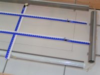
I prefer to use the draw-a-rectangle-and-measure method. Additional tip: use paper rulers (see picture) that are fixed (tape) on one end so you can read the change in length on the other while stretching.
The amount of stretching needed depends on the mylar properties (tensilized or not, thickness, etc...) and on what you want to achieve with the panel (hig/low res, bias etc). My experience it you'll end up somewhere between 0.5 and 3 % in length.
A good way of testing the max stretch is to mark a piece of mylar and stretch it to a certain tension, then release the tension and see if it returns to the original length. Now try 0.5% more etc until you find the point where it doesn't return to the original size anymore. When you stretch your panels at no more than 75% of that limit you can be pretty sure they won't lose tension over time.
Keep also in mind that resonance depends strongly on the 'window size'. So it when you measure it on the tensioning rig, it will increase after you glue it to the stator (smaller size).
I prefer to use the draw-a-rectangle-and-measure method. Additional tip: use paper rulers (see picture) that are fixed (tape) on one end so you can read the change in length on the other while stretching.
The amount of stretching needed depends on the mylar properties (tensilized or not, thickness, etc...) and on what you want to achieve with the panel (hig/low res, bias etc). My experience it you'll end up somewhere between 0.5 and 3 % in length.
A good way of testing the max stretch is to mark a piece of mylar and stretch it to a certain tension, then release the tension and see if it returns to the original length. Now try 0.5% more etc until you find the point where it doesn't return to the original size anymore. When you stretch your panels at no more than 75% of that limit you can be pretty sure they won't lose tension over time.
Attachments
Calvin said:Hi,
a method to measure the tension could be to use a light ball (eg for table tennis) and let it fall from a certain fixed height onto the diaphragm. The membrane will react to this impulse with a sound. The ´bounce´ can be miked and seen on the screen of a oszilloscope or a soundcard-based analyzer. The sound is a dampened (sine-) wave with the membranes resonance frequency. The harder You stretch the higher the frequency, till You reach the point where the diaphragm material starts to flow and the resonance doesn´t go up further.
jauu
Calvin
How about just measuring the height of the rebound?
If you made the window in the stretcher the same size as the free diaphragm area in your speaker you can measure the resonance as it will be in your speaker. The bias voltage will cause it to lower a bit, but you'll be close and consistent.
I F
Hi,
@I-Forgot
I think measuring the precise hight of the rebounce could be a bit difficult. I assume You need precise measuring here because the difference in height will be very small??!! But basically this procedure should work.
Measuring the frequency is imo easier. Even simple listening to the bouncesound, You´re ear will recognize slight differences in frequency.
jauu
Calvin
Hi,
I think that it would be possible to place a dynamic driver close to stretching jig , and try to play various tones with tone generator program , and try to hear or measure the resonant frequency. Even a spectrum analyser and mic may not be needed in this case. Has anybody tried this ?
I think that it would be possible to place a dynamic driver close to stretching jig , and try to play various tones with tone generator program , and try to hear or measure the resonant frequency. Even a spectrum analyser and mic may not be needed in this case. Has anybody tried this ?
Calvin said:Hi,
@I-Forgot
I think measuring the precise hight of the rebounce could be a bit difficult. I assume You need precise measuring here because the difference in height will be very small??!! But basically this procedure should work.
Measuring the frequency is imo easier. Even simple listening to the bouncesound, You´re ear will recognize slight differences in frequency.
jauu
Calvin
Measuring the height would be tricky, but how about measuring the time to bounce? Use a mic to pick up the ball striking the film, or better yet, a piezo electric film sensor placed on the film.
I_F
Use the microphone like a guitar tuner, flick the mylar with your finger and record the damped sine wave oscillation. If you use a soundcard to record the impulse and response, you can simply FFT it and pick out the resonant frequency. You've got a bit of math head of you to determine the resonant frequency vs. tension.
Sheldon
Sheldon
Bazukaz said:Hi,
I think that it would be possible to place a dynamic driver close to stretching jig , and try to play various tones with tone generator program , and try to hear or measure the resonant frequency. Even a spectrum analyser and mic may not be needed in this case. Has anybody tried this ?
I tried this last evening, it works fine.
I layed a stator with readily glued on membrane on top of a low fs/qts woofer (25/0.25, not critical), mounted a measuring mic above it, swept a sine signal from 20 to 100Hz and watched the mic output on a scope. Panel resonance was clearly indicated. I tested 2 others complete panels and all had different fs. I think if this sort of test is done with the exciter driver mounted below the stretcher table the final resonance of ready panel will be pedictable. For correct results the stators will have to be temporary attached to the membran.
- Status
- This old topic is closed. If you want to reopen this topic, contact a moderator using the "Report Post" button.
- Home
- Loudspeakers
- Planars & Exotics
- How to measure diaphragm tension