It's an old thread, but allow me to present my solution to you all.
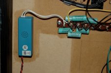
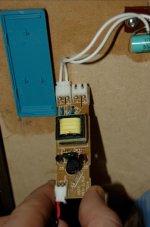
I bought a 'cold cathode fluorescent lamp', or CCFL, the type of colored tubular lamp that kids put inside their computers to show off. They are dirt cheap, maybe $8. Those lamps need a high AC voltage, ...
Kenneth
What level of ac voltage do these little things put out?
Mine give about 1100V RMS. They have a little series capacitor at the output, as a rudimentary current limiter I suppose; if I remove that, I get even higher voltages. Exactly how much, I can't measure anymore without a HV probe.
Because the frequency is so high, one could easily make a multiplier ladder with many stages, and keep the losses down. Using more than ~10 stages at 100/120Hz requires huge capacitors to reduce the losses!
Because the frequency is so high, one could easily make a multiplier ladder with many stages, and keep the losses down. Using more than ~10 stages at 100/120Hz requires huge capacitors to reduce the losses!
Thanks kavermei ,
I have a few of those in a box somewhere, ill have a look, i suppose i could test them with a standard multi by hooking one up to a standard step down trafo of a known step and test the voltage that way.
might be just the thing i need rather than building a complete bias from scratch.
I have a few of those in a box somewhere, ill have a look, i suppose i could test them with a standard multi by hooking one up to a standard step down trafo of a known step and test the voltage that way.
might be just the thing i need rather than building a complete bias from scratch.
Why do you insist to use a trafo? You could design a safe cascade multiplier supplied directly from the mains outlet.
I wouldn't call that safe. How can you possibly say that?? If you're not careful, or the socket is miswired, that'll put live mains on both your stators (through the audio trans secondaries).
You would pretty much need to make your speakers a Safety Class II device, to avoid blatantly violating all possible safety specs for electric equipment.
Finally, it'll put DC on the power grid, which is not very polite towards other equipment.
Am I missing something here??
Kenneth
Let me comment from a electrical engineering background:
1) Running transformers backwards. It has been mentioned before but when you do that at line frequencies (50/60Hz) you will saturate the core thereby creating a short circuit and burning up the transformer: the smoke signaling")
It can be done but the frequency of the input signal has to go up by the same factor as the voltage ratio of the transformer.
2) There is no problem creating a high bias voltage using a cheap 110/220V in and 220V out small (5W or so) isolation transformer and a 8-10 stage multiplying stack using 1N4007 diodes and 100nF 630V capacitors. Since each diode and capacitor only has 1 times the rectified 220V across it there is no need for fancy multi-kilovolt diodes or capacitors.
1) Running transformers backwards. It has been mentioned before but when you do that at line frequencies (50/60Hz) you will saturate the core thereby creating a short circuit and burning up the transformer: the smoke signaling
It can be done but the frequency of the input signal has to go up by the same factor as the voltage ratio of the transformer.
2) There is no problem creating a high bias voltage using a cheap 110/220V in and 220V out small (5W or so) isolation transformer and a 8-10 stage multiplying stack using 1N4007 diodes and 100nF 630V capacitors. Since each diode and capacitor only has 1 times the rectified 220V across it there is no need for fancy multi-kilovolt diodes or capacitors.
the one major importance for using a transformer (that nobody has ever mentioned) is that it limits the amount of current able to be drawn from the line, should any thing short out.if you short out the line there is a potenial 10,000 amps of current draw and once that arc gets started your not going to be able to readily stop it.not so true with only 1 amp or less. jer
Personally each way as fine as long as your careful. I modded a stax electrostatic power unit to use a higher bias but that only dealing with a jump from 240 to 580 v dc. when dealing with the big boys i is vital that safety is the number one priority.
Of course self biasing from the amp speaker volage and using a large number of stages up rectifiy and up the dc voltage has been done before but is it as good?
Of course self biasing from the amp speaker volage and using a large number of stages up rectifiy and up the dc voltage has been done before but is it as good?
This is made by commercial designs also so I hope I'm not overlooking something, but please comment...
Two factors make it safe:
1. The audio trafo gives the DC isolation needed to protect your power amplifier.
2. Limit the highest possible current with resistors both to the membrane and to the middle point of the audio trafo’s speaker side. The latter to eliminate the risk of electric shock Kenneth warns about.
If you use a power trafo anyway make sure to pick one without any connection between primary and secondary coil.
More on safety
You do not normally use transformers to limit current. They have limitations of cause, but in this case it is important to design your high voltage supply to limit current to below a couple of mA to avoid risk of eclectic shock. I use 500kΩ to connect the audio transformers (limits to 0.5mA) and 10MΩ to the membranes.
Running backwards
Running a power transformer backwards is not a good idea if you plan to connect it to the mains. The coil on the secondary side is designed for low voltage and relatively high current, for example 12V 5A (=60VA). If you connect this side (designed to be a source of energy with low inner serial impedance) to the mains (240Vac) you will likely have a short lived smoky 1000W electric fire.
This last weekend I designed a variable bais supply.
Not sure on the maxium output voltage as i haven't built a resistor divider to measure with yet.
It does 0 to 2kv at least and can do more by adding more stages.
It really works as I accidently found out today.
It's really simple and a fairly safe swiitcher that runs off of a 16vdc supply.
The best part is it is 0 to (v)kv variable in order to get the highest voltage possible before arcing.
I will post the schematic as soon as I get it drawn up in circuitmaker. jer
Have you tried to disconnect the high voltage supply from the outlet while listening?
Can you observe any change (before the discharge takes its toll of cause)?
Speaking for myself, I can't. I use a very large series resistor (400 Mohm), forming a ~1Hz lowpass together with my panel capacitance. No issues of hum etc.
Once the diaphragm is charged, the HV supply delivers mere nano-amps.
Kenneth
You can use a transformer to step up but operate the winding at the value it was designed for:
use one transformer to step 110 down to 24 (or other available value) THEN step the 24 v up to 110 (or 220) for voltage multiplication
This is not a new idea...VTVM supply used this for filament and 170VDC from two common transformers (110V:6.3V)...more than 40 years ago
isolation and 110 (or 220) AC
Another idea would be a voltage sense transformer 575V:110V. use that backwards for 110V:575V
- Status
- This old topic is closed. If you want to reopen this topic, contact a moderator using the "Report Post" button.
- Home
- Loudspeakers
- Planars & Exotics
- High Voltage Bias for DIY Electrostatics