ESLs generally require balanced drive (i.e. push-pull) on two stators. How do you intend to connect this to an ESL driver?
You also need a HV bias source for the diaphragm...
Try something like this:
http://www.headwize.com/projects/showfile.php?file=gilmore2_prj.htm
Download a copy of SwitcherCAD and learn how to use it. You can simulate the circuit and get a pretty good idea what it will do.
I_F
You also need a HV bias source for the diaphragm...
Try something like this:
http://www.headwize.com/projects/showfile.php?file=gilmore2_prj.htm
Download a copy of SwitcherCAD and learn how to use it. You can simulate the circuit and get a pretty good idea what it will do.
I_F
LT's Spice is great but not setup for learning Spice from, buy a book on learning electronics with Spice, LtSpice will be 99%+ compatable
you can download other, less capable, "Demo" versions of Spice from the big guys and just use the documentation with LtSpice
you have to join Yahoo to acess the really great LtSpice user's group, many example files, Spice experts and the main LtSpice programmer are there - just don't expect them to teach you Spice basics
the "uknown subcircuit" error means you are calling for devices that aren't in the supplied model libraries (\lib directory), adding spice models in LtSpice is easier than many other Spice programs but you do need to read the help - if you enter the schematic in the editor and select devices from the tool bar component pull down (the "and gate" symbol) you should have no probelms - don't expect to run any random netlist in any Spice without finding all of the required models/subcircuits and adding them to the library
Thanks a lot ,
LTSpice really helps.
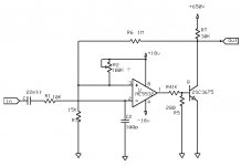
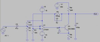
I tried to simulate the following circuit.I built a prototype and tested it , but the distortion levels are around 0.2% from 50Hz to 20Khz.
What is the problem ? Circuit design flaws , or wrong type of transistor ?
Regards ,
Lukas
LTSpice really helps.
I tried to simulate the following circuit.I built a prototype and tested it , but the distortion levels are around 0.2% from 50Hz to 20Khz.
What is the problem ? Circuit design flaws , or wrong type of transistor ?
Regards ,
Lukas
Attachments
in LtSpice the default setting is to compress the waveform data - this causes distortion in the analysis of the sim
add the spice directive:
.option plotwinsize=0
to the schematic with the ".op " button at the right of the toolbar
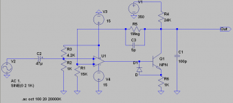
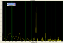
my sim of your circuit using the (inadequate V) mje340 which I think came with LtSpice and a higher gain, high speed Lt1115 op amp gives ~ -110 dB 2nd harmonic 140Vrms @10KHz
I couldn't find a 2sc3865/6 model with google - to share you can put the added models on the schematic with the .op button and post the .asc circuit file by changing the file extension to .txt and attaching to your post
please use .png or .gif for schematics, jpeg renders part # unreadable
add the spice directive:
.option plotwinsize=0
to the schematic with the ".op " button at the right of the toolbar
my sim of your circuit using the (inadequate V) mje340 which I think came with LtSpice and a higher gain, high speed Lt1115 op amp gives ~ -110 dB 2nd harmonic 140Vrms @10KHz
I couldn't find a 2sc3865/6 model with google - to share you can put the added models on the schematic with the .op button and post the .asc circuit file by changing the file extension to .txt and attaching to your post
please use .png or .gif for schematics, jpeg renders part # unreadable
Thanks for help ,
The problem is not LTSpice related , because i really built it.
I used NE5532 for a driver IC with 2SC3866 transistor.Sound card was used as both oscilloscope and signal generator(it produces ~0.03% THD from output to input).
For measuring i used SpectraPLUS program.
THD+N was around 0.06% at 1 khz but ~0.2% at 5 khz and higher.
I have also tried generating square wave , but it wasn't even close to it at any frequency.Probably sound card is not capable of generating square too.
The little amp produced ~85Vrms until distortion started to rise quickly.
Transistor's datasheet :
http://www.alldatasheet.com/datasheet-pdf/pdf/82610/FUJI/2SC3866.html
I have also found one interesting direct drive schematic at www.shackman.de .Unfortunately , its description is in german .
.
I could share it if you are interested.
Regards ,
Lukas
The problem is not LTSpice related , because i really built it.
I used NE5532 for a driver IC with 2SC3866 transistor.Sound card was used as both oscilloscope and signal generator(it produces ~0.03% THD from output to input).
For measuring i used SpectraPLUS program.
THD+N was around 0.06% at 1 khz but ~0.2% at 5 khz and higher.
I have also tried generating square wave , but it wasn't even close to it at any frequency.Probably sound card is not capable of generating square too.
The little amp produced ~85Vrms until distortion started to rise quickly.
Transistor's datasheet :
http://www.alldatasheet.com/datasheet-pdf/pdf/82610/FUJI/2SC3866.html
I have also found one interesting direct drive schematic at www.shackman.de .Unfortunately , its description is in german
.I could share it if you are interested.
Regards ,
Lukas
Attachments
it's hard to say what the 2sc3866 is is capable of distortion-wise,
op amp open loop gain is falling with increasing frequency and output Q Zcb nonliear current is rising too, the distortion rise isn't too suprizing
Resistor bias causes the Q to work harder, maybe a ccs would help
often higher bias current reduces distortion, may speed up output Q too
op amp open loop gain is falling with increasing frequency and output Q Zcb nonliear current is rising too, the distortion rise isn't too suprizing
Resistor bias causes the Q to work harder, maybe a ccs would help
often higher bias current reduces distortion, may speed up output Q too
ESL Headphone Direct Drive Solid State Amp
Stumbled on an ESL headphone amp circuit in a TI application note I thought might be of some interest.
I attached a copy of the relevent pages in case the link disappears in the future...hate it when that happens.
http://www.ti.com/lit/an/snaa046/snaa046.pdf
Stumbled on an ESL headphone amp circuit in a TI application note I thought might be of some interest.
I attached a copy of the relevent pages in case the link disappears in the future...hate it when that happens.
http://www.ti.com/lit/an/snaa046/snaa046.pdf
Attachments
Hi,
that one´s on for quite a time ;-)
What I find very annoying is the fact that there are a couple of failures in the schematic.
More and more I get the impression, that circuits presented in application notes never made it even to the breadboard, but are just intellectual baby spoo.
It is for at least 20 years now possible to cut and paste correct schematics into a document.
Why are there still major faults in many and even simple schematics of global players like TI, LT et al?
jauu
Calvin
What I find very annoying is the fact that there are a couple of failures in the schematic.
More and more I get the impression, that circuits presented in application notes never made it even to the breadboard
Hello Calvin,
I must admit I didn't give the circuit more than a quick glance since it is not really of interest to me at this time. But, I posted it since I figured others might be in search of such a circuit. If it is not too involved, and you have the time, you might describe the required corrections to the schematic to achieve a working circuit.
A 60 second look and I noticed:
1) the -15 VDC supply was mislabeled as +15 VDC
2) the balance resistor R11 is missing from the schematic
3) the +OUT line fails to connect to the drain of Q2
4) Q1 & Q2 most likely IRF720, not IRF72
Are these the type of things you are talking about?
or are you saying there is something fundamentally wrong with the circuit.
I know National used to provide PC board layouts and even demo boards for some circuits in their application notes. This provided some level of confidence that the circuits would work as described. But, this was certainly the exception rather than the rule.
Last edited:
Hi,
Several years ago I have built successfully a rather simple direct drive amp.
The op amp was driving a high voltage FET in class A. Current source was made by using another FET and string of LEDs.
The amp is lying somewhere in the garrage but schematic seems to be lost.
I could dig my archives if anybody is interested in.
BTW - Calvin - a long time
Regards,
Lukas.
Hi,
the list of corrections are what I found also.
In addition one should check the wattage of the drain resistors R8, R9.
Since the circuit runs in class-A, just 3W will be low.
My gut-feeling says, stay well clear and enjoy the fireworks.
Again, since running in class-A the Pot R11 takes on the current of both MOSFETs, hence it wattage needs to be observed. But in any case is it a rather bold idea to run loads of currents over the wiper of an pot.
Stability of the amp needs also to be observed. Adding external gain stages and include them into the feedback loop and driving capacitve loads a local loop (here C1) is almost always required. It might be, that a modification of the local loop is required to get the amp stable.
One might want to check what is happening at the amps outputs when starting and shutting down the amp.
The Bias generating resistor-networks values are weird. Here a Bias voltage of just 200V results, which must lead to gross distortions as soon as the signal voltage reaches or superseeds these 200V. A correct coltage would be >=400V or at least as high as the ESL-panel allows for.
R15 could be much smaller, or omitted with alltogether and optionally R16 could be raised in value up to ~1Meg.
jauu
Calvin
I have messed with these types of circuits in spice and on the bench.
I have built a small version to prove the concept.
But I haven't made one large enough to drive an ESL nor have I finished my ES headphones yet.
Here are a few designs that I posted a while back,
http://www.diyaudio.com/forums/head...discrete-class-headphone-amp.html#post2596223
I drove a Piezo element to very high volumes on a 170v supply and quite cleanly as well,I might add.

jer
I have built a small version to prove the concept.
But I haven't made one large enough to drive an ESL nor have I finished my ES headphones yet.
Here are a few designs that I posted a while back,
http://www.diyaudio.com/forums/head...discrete-class-headphone-amp.html#post2596223
I drove a Piezo element to very high volumes on a 170v supply and quite cleanly as well,I might add.
jer
I have messed with these types of circuits in spice and on the bench.
I have built a small version to prove the concept.
But I haven't made one large enough to drive an ESL nor have I finished my ES headphones yet.
Here are a few designs that I posted a while back,
http://www.diyaudio.com/forums/head...discrete-class-headphone-amp.html#post2596223
I drove a Piezo element to very high volumes on a 170v supply and quite cleanly as well,I might add.
jer
You might find this interesting. Go to page 4
http://www.edn.com/file/15429-101404di.pdf?force=true
I believe 2 junctions are missing at the + and - 1000V inputs and the junction of R23 and the output should not be there. Scale this back to +/- 400 and it might be about right. Of course you need a total of 4 (2 inverting) for stereo push/pull.
G²
Thanks for the links to the National Semiconductor / Texas Instruments Application note and to the EDN article. I agree that stability could be an issue driving the capacitive load.
It's a pity the semiconductor companies don't have the time to prototype the application circuits properly.
A rather weak excuse for the schematic errors is that they can be redrawn by the documentation / marketing department to conform to a 'company standard' so cut and paste may not be an option. Inter department rivalry and politics can also cause grief.
I am currently working on the design of a discrete high voltage direct drive amplifier that uses the capacitive load for frequency compensation. I am in the design stage and still need to prototype the circuit. I am using a push pull class A output stage using stacked N and P channel MOSFETS running in class A with a quiescent current of about 10 mA. Supply voltage about +/- 950 V. Peak single ended output voltage about +/- 920 V.
- Status
- This old topic is closed. If you want to reopen this topic, contact a moderator using the "Report Post" button.
- Home
- Loudspeakers
- Planars & Exotics
- ESL Headphone direct drive