Thank's for the answer Solhaga !
You have answered to more than my question, great !
I stupidly forgot that the coil has to stay in the flux coming from the iron all the time, so i do not have to bother about the flux between the magnet.
Now, i also know that there is no need for the iron to "over hang" the magnets.
Another question, with such a high flux you are getting with your motor and the small thickness of your iron plates, and a 3mm gap, nothing bends ?
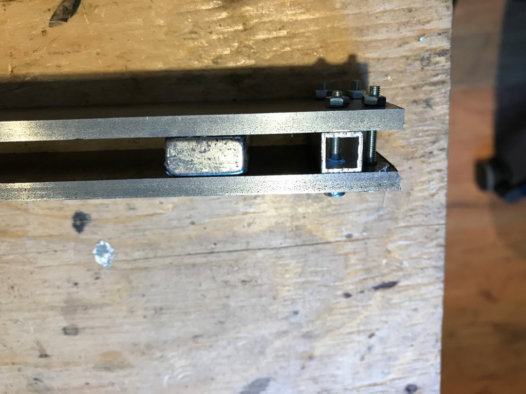
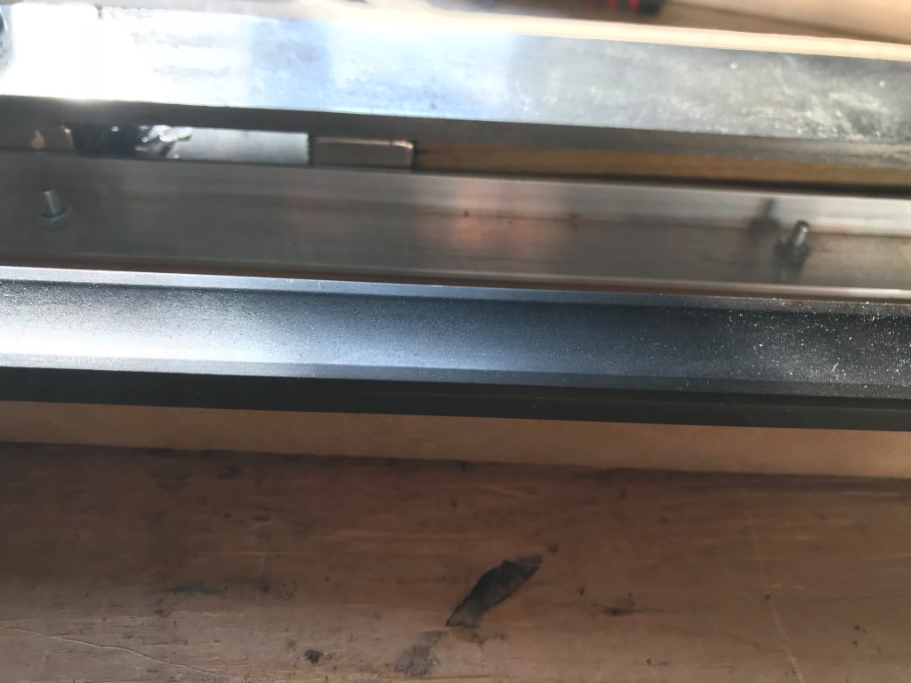
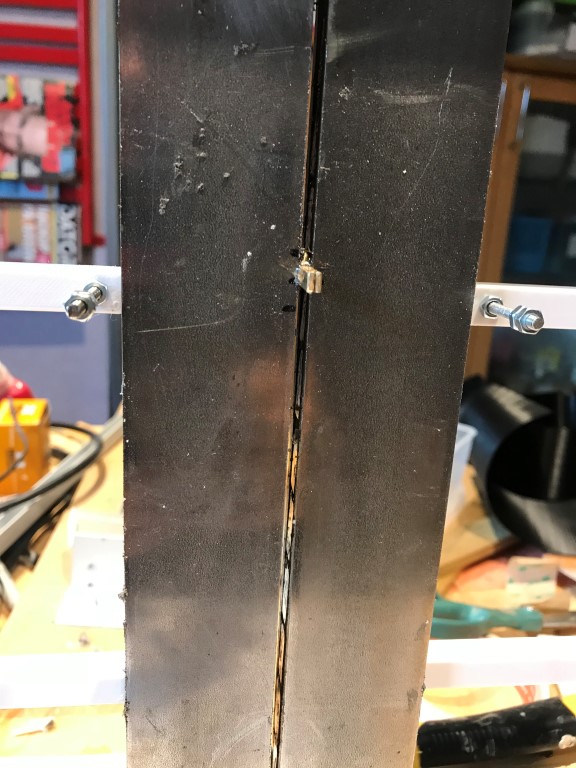
I would say that a 20 mm wide iron bar will bend.
Depending on how long it is of course.
That´s why I use 40 mm by 5 mm bars.
Downside is that it will require double the amount of magnets and of course result in a wider motor.
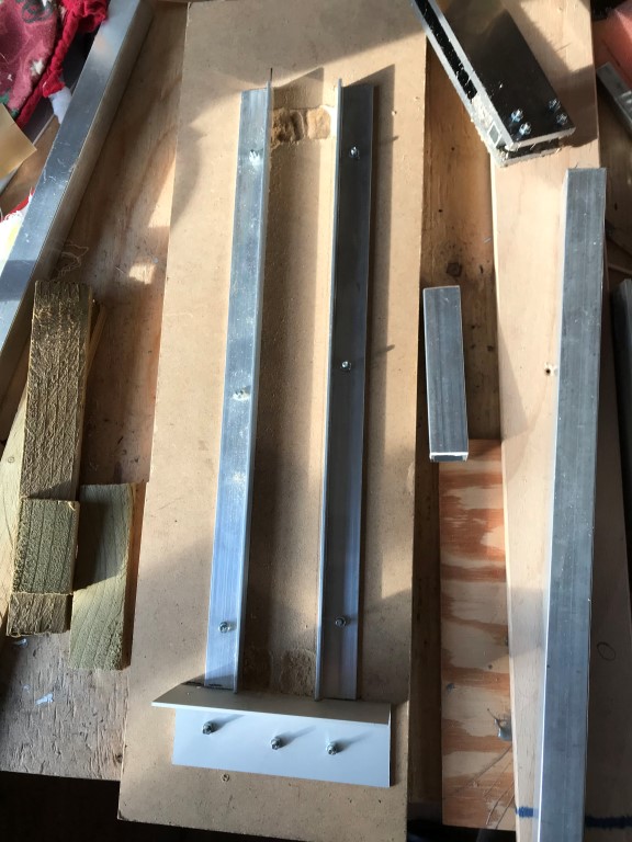
Some pictures of making my simple motor above:
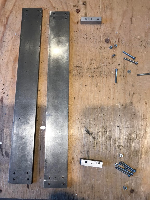
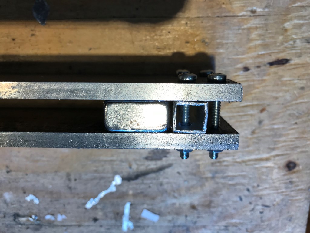
Iron bars and aluminium stops::
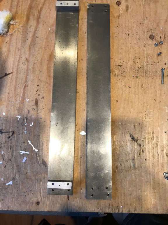
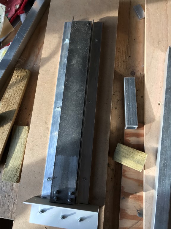
Ready for the first magnet:
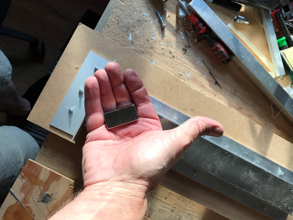
That was easy:
In its right place with some epoxy:
As the next magnet will repel, I need a mounting jigg:
Next magnet must have the right polarity.
If I hold it in my hand, it will will flip right.
And then just force it down:
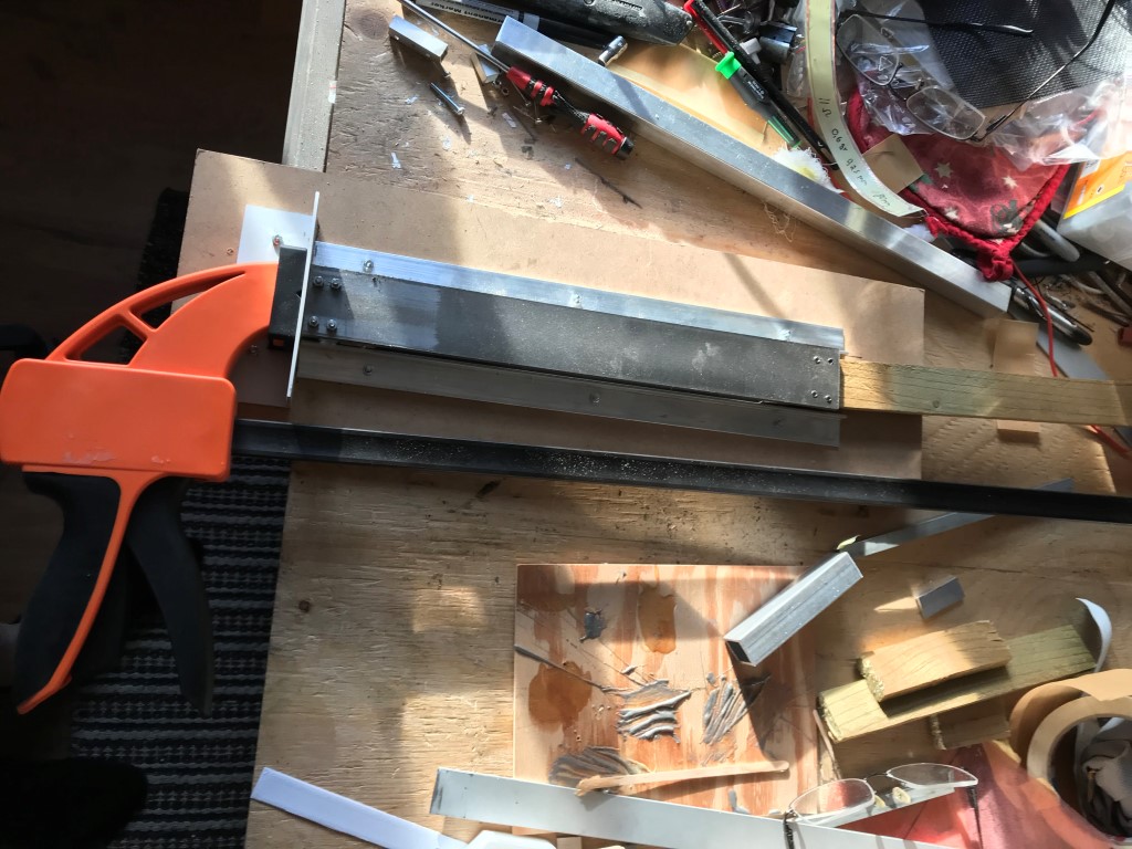
Some epoxy before the final destination:
Now I will have to wait a couple of hours before the next magnet can be mounted.
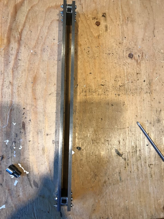
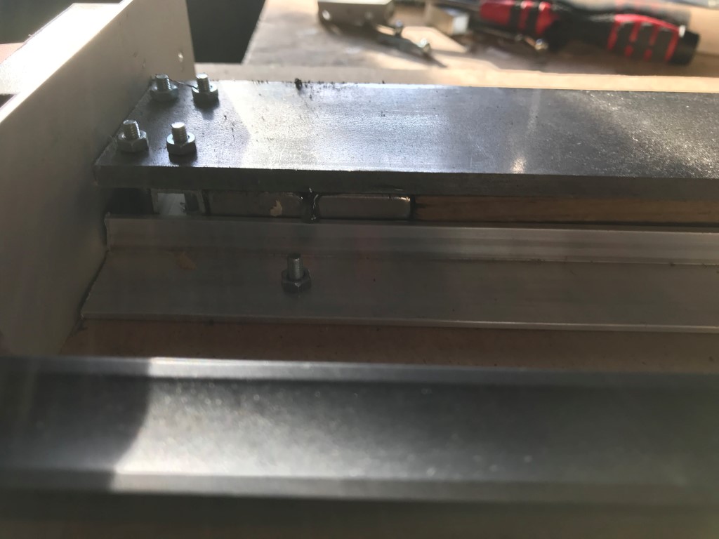
The tricky part will be when I mount the two legs of the motor together.
I'm thinking of using rails and then slide the two parts together and then ---
  BAAM!
BAAM!
Depending on how long it is of course.
That´s why I use 40 mm by 5 mm bars.
Downside is that it will require double the amount of magnets and of course result in a wider motor.
Some pictures of making my simple motor above:
Iron bars and aluminium stops::
Ready for the first magnet:
That was easy:
In its right place with some epoxy:
As the next magnet will repel, I need a mounting jigg:
Next magnet must have the right polarity.
If I hold it in my hand, it will will flip right.
And then just force it down:
Some epoxy before the final destination:
Now I will have to wait a couple of hours before the next magnet can be mounted.
The tricky part will be when I mount the two legs of the motor together.
I'm thinking of using rails and then slide
the two parts together and then --- BAAM! Another question, with such a high flux you are getting with your motor and the small thickness of your iron plates, and a 3mm gap, nothing bends ?
Well.
Front down:
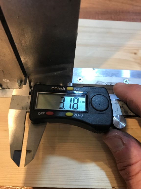
Front mid:
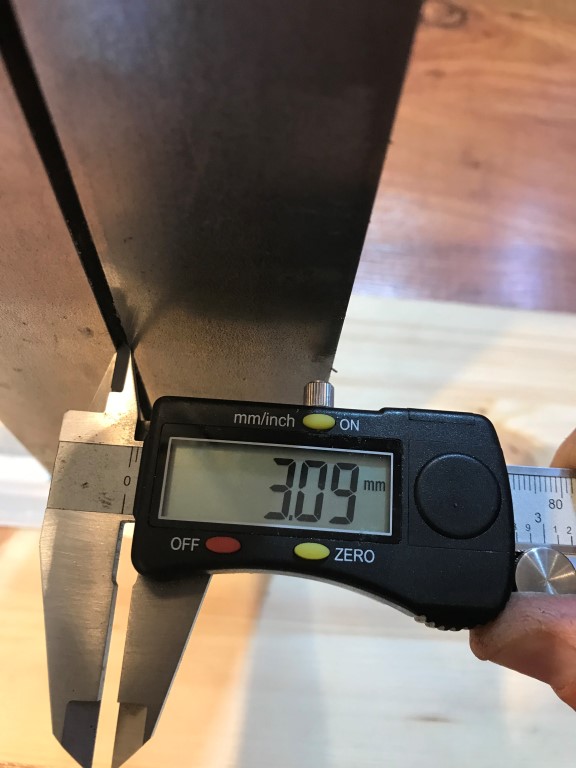
Front up:
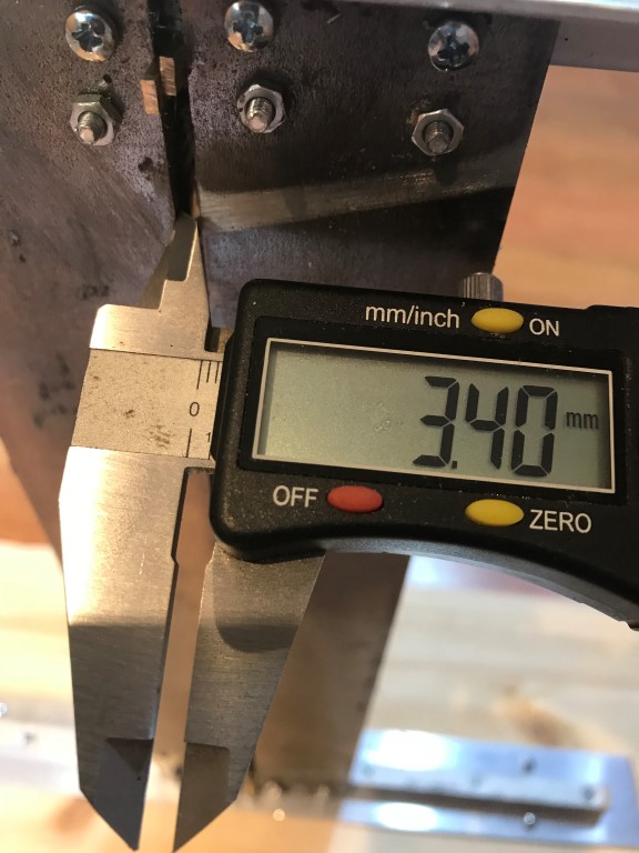
Back down:
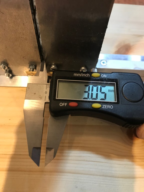
Back mid:
Back up:
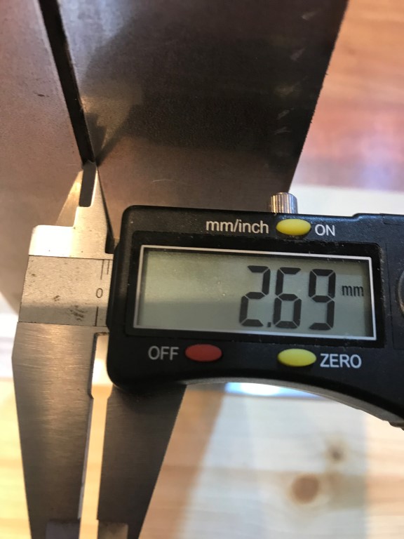
2,69 mm is too little, I'll probably have to insert 3,5 mm spacers or even 4,0 mm.
On the other hand, I can insert an additional spacer between the mid (210 mm) and treble membranes (80 mm)
Last edited:
Well, just for the fun of it:
An externally hosted image should be here but it was not working when we last tested it.
An externally hosted image should be here but it was not working when we last tested it.
But the plot was the same as above:
An externally hosted image should be here but it was not working when we last tested it.
Even it can be tweaked to a higher or wider field, I guess it isn't worth the effort neither design nor build wise.
i did not know you where into these to
") 0r only sims
0r only sims I would say that a 20 mm wide iron bar will bend.
Depending on how long it is of course.
That´s why I use 40 mm by 5 mm bars.
Downside is that it will require double the amount of magnets and of course result in a wider motor.
Some pictures of making my simple motor above:
Iron bars and aluminium stops::
Ready for the first magnet:
That was easy:
In its right place with some epoxy:
As the next magnet will repel, I need a mounting jigg:
Next magnet must have the right polarity.
If I hold it in my hand, it will will flip right.
And then just force it down:
Some epoxy before the final destination:
Now I will have to wait a couple of hours before the next magnet can be mounted.
The tricky part will be when I mount the two legs of the motor together.
I'm thinking of using rails and then slide
yes 20mm will bend with that kind of magnet
i had a few bending with only 40x20x1 magnets over a length of 500mm steeli did not know you where into these to
I will eventually start a new thread when I have got a little bit further with my Rubanoid, meanwhile I only answered the FEMM question from ndhennin.
I will eventually start a new thread when I have got a little bit further with my Rubanoid, meanwhile I only answered the FEMM question from ndhennin.
looking forward, since i want to do some more ruba to, they are even more efficient then the AMT. most certainly with that HUGE motor.
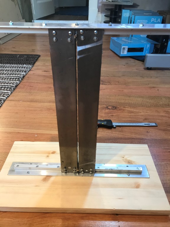
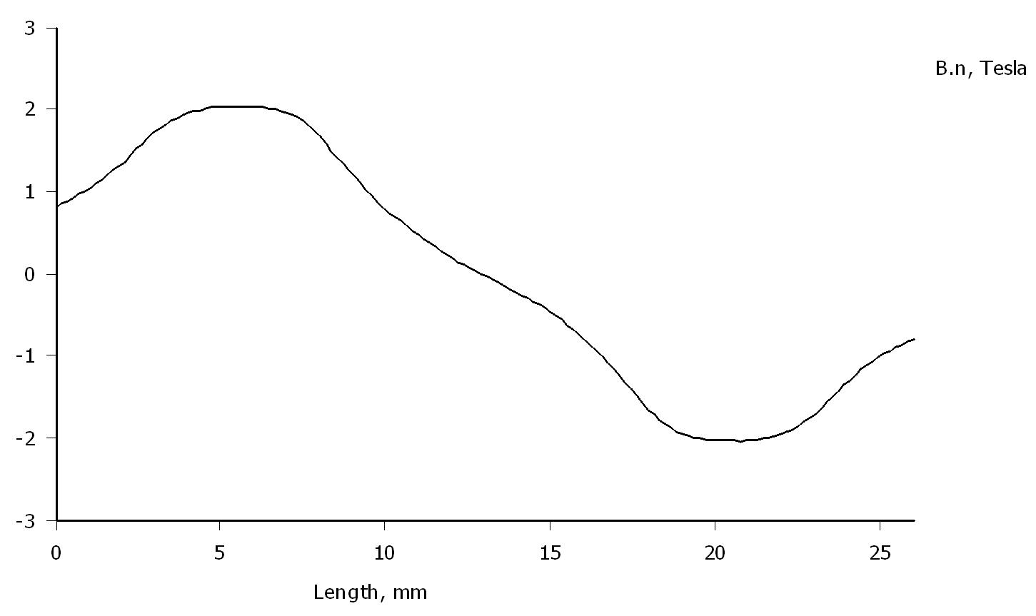
Looking forward too solhaga. You have a very interesting way of assemblying the motor and a very powerfull motor there. How much did you simulate it has in T?
I use a more invasive and messy way of assembly where you have to be very carefull with your fingers...
As a hint, you can observe now that the bars bends only (if they are strong enough) when you join the whole magnet motor. If the gap remains constant for a week then you are good to go, if not.... add reinforcements, like thick U shaped of harder steell and bolt them to each side of the magnets.
It will become a bit bulky (at least 5kg in plus) but will hold.
Cant wait to hear you impressions and see your results.
Cheers
Sergiu
Looking forward too solhaga. You have a very interesting way of assemblying the motor and a very powerfull motor there. How much did you simulate it has in T?
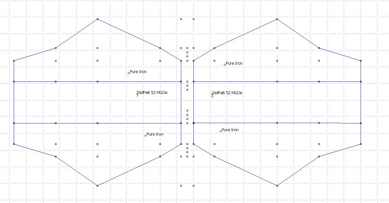
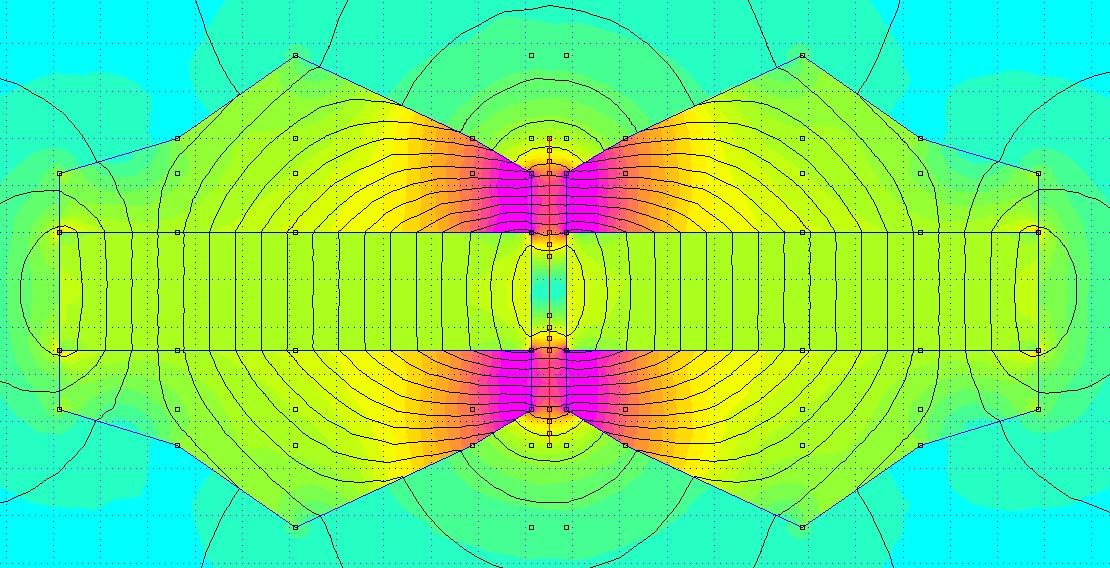
1.8 T. Look at the first motor in post #1238
As a hint, you can observe now that the bars bends only (if they are strong enough) when you join the whole magnet motor. If the gap remains constant for a week then you are good to go, if not.... add reinforcements, like thick U shaped of harder steell and bolt them to each side of the magnets.
It will become a bit bulky (at least 5kg in plus) but will hold.
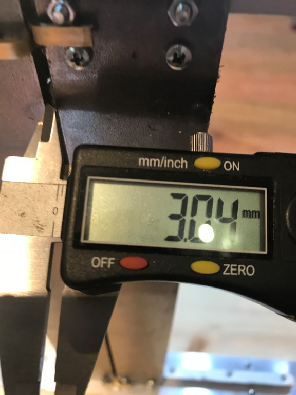
The gap width is stable, but I've put an extra 3 mm spacer between the mid membrane and the tweeter membrane just to be sure:
Bonjour,
Après toute ces années de questionnement et de recherchepersonnel j'ai décidé de vendre les équipages mobiles (circuit et membranes) dumodèle Janus 50. Il s'agit des versions originales fabriquées par MrDeminière et jamais montées car faute de moyen pour me procurer tout lereste des éléments constitutif de ce transducteur sonore.
Sur son site elles sont vendues à 300E; je suis ouvert auxpropositions si toute fois cela intéresse quelqu’un. :wink:
Dans l'attente, cordialement
=========
Hello,
After all these years of questioning and personal research I decided to sell the mobile crews (circuit and membranes) of the Janus 50 model. These are the original versions manufactured by Mr Deminière and never mounted because of lack of means to get all the rest of the constituent elements of this sound transducer.
On its site they are sold at 300 Euros; I am open to proposals if anyone is interested. : Wink:
In the meantime, cordially
I am starting to work on the construction : grinding the metal at the moment.
A question poped up in my mind concerning the connexion between the coils ans the wires coming from the amp : I am going to make the coil with aluminium wire : 0,175 mm for the diameter. Is this section big enough to link the coil to the wires coming from the amp ? sounds thin no ?
A question poped up in my mind concerning the connexion between the coils ans the wires coming from the amp : I am going to make the coil with aluminium wire : 0,175 mm for the diameter. Is this section big enough to link the coil to the wires coming from the amp ? sounds thin no ?
1.8 T. Look at the first motor in post #1238
The gap width is stable, but I've put an extra 3 mm spacer between the mid membrane and the tweeter membrane just to be sure:
sick amount of Tesla
now comes the fidling job... 3mm sounds big but with paper over a big distance it is still is pretty small looking forward though
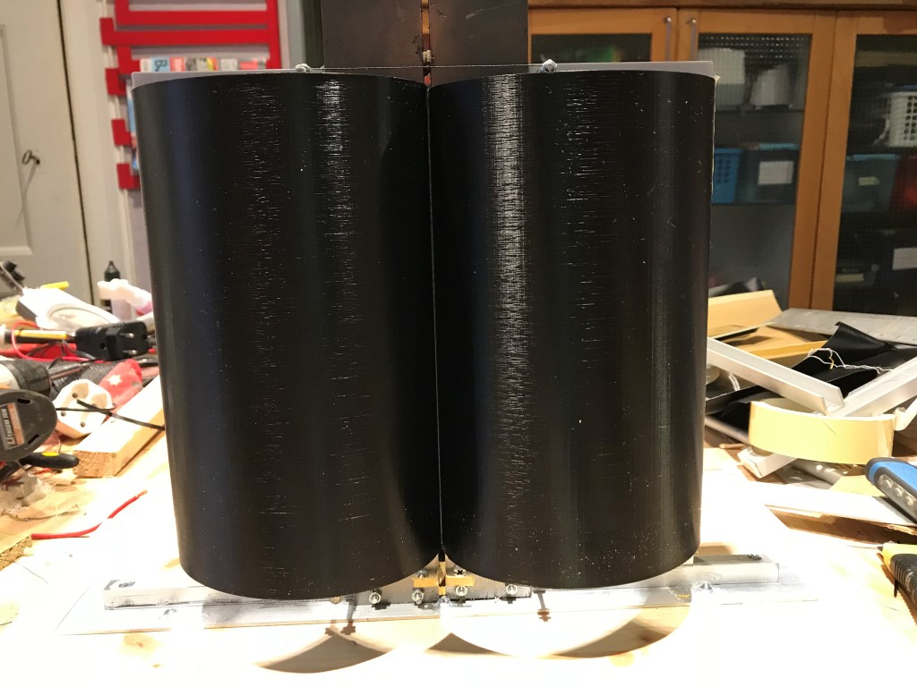
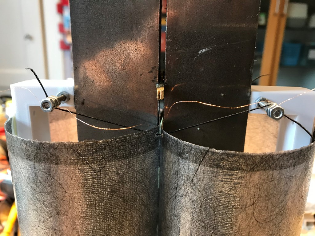
I've made two types of membranes: one 3D printed and one laminated carbon fibre.
3D printed:
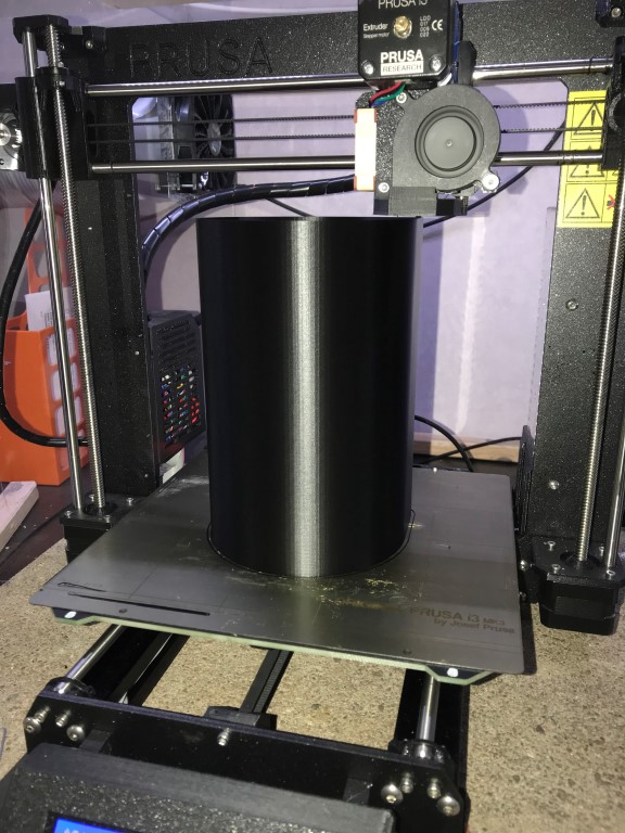
Mounted:
Sounded like this .
.
I had no suspension on this one, so it wasn't in the middle of the gap, hence the scratching sound.
It measured like this (1W @ 1m):
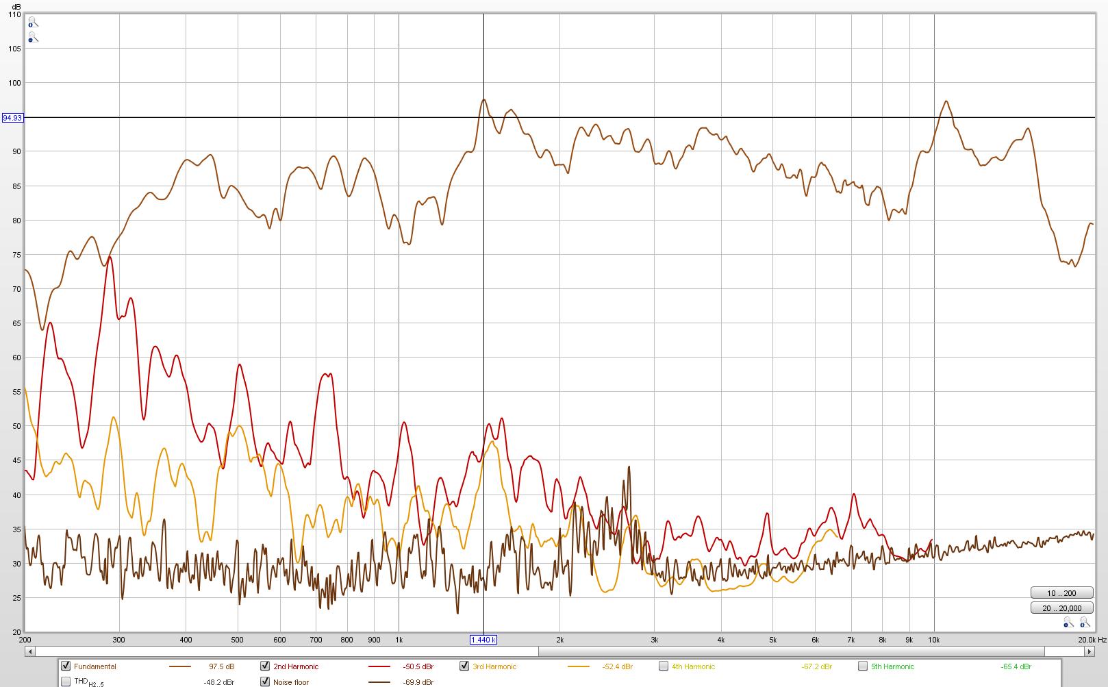
Too high distortion for my liking, so I decided to laminate some carbon fibre, 8 gr/m2.
And at the same time make a smaller membrane, this time with suspension:
They sounded like this (200 Hz cut off).
I measured it, but thought that the distortion still was too high.
So I put some dampening inside.
It then measured like this (1 W, 0,25 m):
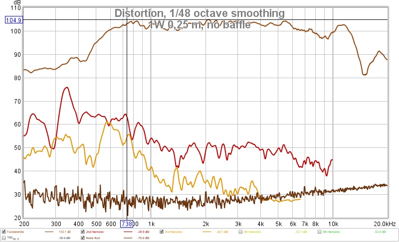
Still too much distortion and not enough SPL in the lows.
In the highs I was thinking of designing a tweeter anyway.
So I needed to make the suspension better,
experiment with other membrane materials,
read all pages of this thread,
and ..
Then I realized that it will take some time and effort to get this right and making them better than SLAM!
I wanna do other stuff, like listening to my fantastic SLAM! speakers and playing with my Prusa 3D printer, now with five color/material printing.
By the way, SLAM! sounds like this in a my setup.
3D printed:
Mounted:
Sounded like this
.I had no suspension on this one, so it wasn't in the middle of the gap, hence the scratching sound.
It measured like this (1W @ 1m):
Too high distortion for my liking, so I decided to laminate some carbon fibre, 8 gr/m2.
And at the same time make a smaller membrane, this time with suspension:
They sounded like this
(200 Hz cut off).I measured it, but thought that the distortion still was too high.
So I put some dampening inside.
It then measured like this (1 W, 0,25 m):
Still too much distortion and not enough SPL in the lows.
In the highs I was thinking of designing a tweeter anyway.
So I needed to make the suspension better,
experiment with other membrane materials,
read all pages of this thread,
and ..
Then I realized that it will take some time and effort to get this right and making them better than SLAM!
I wanna do other stuff, like listening to my fantastic SLAM! speakers and playing with my Prusa 3D printer, now with five color/material printing.
By the way, SLAM! sounds like this
in a my setup.- Home
- Loudspeakers
- Planars & Exotics
- A DIY Ribbon Speaker of a different Kind