Hello.
Made a membrane of paper Palazzo (for pastels) 160gr \ m 40% cotton.
It sounds a bit quieter than 120 gr / m usual white.
But the sound is much more interesting, cleaner.
Tried to find 120 gr \ m with cotton, until unsuccessfully.
I also make the lead wires from Litcendrat (15 conductors) in a silk shell.


sergiu2009 what filter did you do?
I cut Ruban only from below 500 Hz.
Ha nice i used this kind of paper to once, it is sort of ribbed, what i did what use the striped horizontal so it gives the whole thing bit more strength, that paper not sure what it was but looks a bit like this was the best i had, it came from an art store. it was light and rather rigid if you used it in that one direction only. rotate it 90 degrees and it was floppy
Resonance, distortion
Hi,
I step forward with resonance and distortion problem.
Both of my prototype diaphragm (Canson paper and Xerox never tear) had similar behavior.
Resonate one low freq, and there is a big distortion on that frequency and a multiplication of it.
After try several things without real success I read again the patent US4903308 and implement solutions mentioned there.
The Canson paper distortion almost disappear and Xerox (more floppy material) improves a lot.
The phenomena and one solution is clearly written in the patent, and the described solutions works for me.
Wrine implement similar strips earlier.
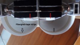
I tried also with foam tape it was not working, fiber glass works.
I made a video of Xerox vibration (around 37Hz):
YouTube
"The present transducer as best seen in FIG. 1 will
have a resonant frequency dependent on the specific
transducer size and the material employed.As shown in
FIGS. 1 and 5, parallel strips of damping tape 73 are
adhered at predetermined locations on the inside of
each web end portion 24a, 24b, 26a and 26b. The strips
of tape, preferably made of a woven fiberglass such as is
found in strapping tape, aids in flattening the amplitude
response and reduces harmonic distortion resulting
from the device’s resonant frequency and its multiples.
Best results have been obtained with a damping tape
mass of about g of the mass of the diaphragm 22, divided
into strips spaced equidistantly apart from near the end
of each web portion to the edge of the central dia
phragm expanse. While three parallel damping strips
are shown, it will be appreciated that an increased num
ber of parallel damping strips spaced equidistantly but
closer together also works well."
Other thing is the damping of "elastomeric cords":
"The length of cord on each side of the expanse as indicated
at 65 in FIG. 2 determines the low frequency below
which the frequency response of the diaphragm is atten
uated. Such attenuation is desirable because the lower
frequency response in a diaphragm has a greater ampli
tude and must be attenuated to improve the overall
response. It has been determined that a cord length of 1;
inch, with the cord fastened l inch away from each side
of the expanse, satisfactorily attenuates frequencies
below 100 Hz."
Hi,
I step forward with resonance and distortion problem.
Both of my prototype diaphragm (Canson paper and Xerox never tear) had similar behavior.
Resonate one low freq, and there is a big distortion on that frequency and a multiplication of it.
After try several things without real success I read again the patent US4903308 and implement solutions mentioned there.
The Canson paper distortion almost disappear and Xerox (more floppy material) improves a lot.
The phenomena and one solution is clearly written in the patent, and the described solutions works for me.
Wrine implement similar strips earlier.
I tried also with foam tape it was not working, fiber glass works.
I made a video of Xerox vibration (around 37Hz):
YouTube
"The present transducer as best seen in FIG. 1 will
have a resonant frequency dependent on the specific
transducer size and the material employed.As shown in
FIGS. 1 and 5, parallel strips of damping tape 73 are
adhered at predetermined locations on the inside of
each web end portion 24a, 24b, 26a and 26b. The strips
of tape, preferably made of a woven fiberglass such as is
found in strapping tape, aids in flattening the amplitude
response and reduces harmonic distortion resulting
from the device’s resonant frequency and its multiples.
Best results have been obtained with a damping tape
mass of about g of the mass of the diaphragm 22, divided
into strips spaced equidistantly apart from near the end
of each web portion to the edge of the central dia
phragm expanse. While three parallel damping strips
are shown, it will be appreciated that an increased num
ber of parallel damping strips spaced equidistantly but
closer together also works well."
Other thing is the damping of "elastomeric cords":
"The length of cord on each side of the expanse as indicated
at 65 in FIG. 2 determines the low frequency below
which the frequency response of the diaphragm is atten
uated. Such attenuation is desirable because the lower
frequency response in a diaphragm has a greater ampli
tude and must be attenuated to improve the overall
response. It has been determined that a cord length of 1;
inch, with the cord fastened l inch away from each side
of the expanse, satisfactorily attenuates frequencies
below 100 Hz."
Attachments
Hi Oleg,
Video shows Xerox never tear 125g/m2,
It is more flexible than 125g/m2 Canson paper.
The paper has similar vibration, Xerox more visible.
I do not think the long gum is better since it is supported quite close when it is working better. In the patent there is recommendation for lengths.
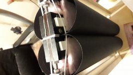
On picture you can see Canson paper with fiber glass tape and with foam supported gum.
Video shows Xerox never tear 125g/m2,
It is more flexible than 125g/m2 Canson paper.
The paper has similar vibration, Xerox more visible.
I do not think the long gum is better since it is supported quite close when it is working better. In the patent there is recommendation for lengths.
On picture you can see Canson paper with fiber glass tape and with foam supported gum.
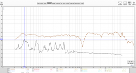
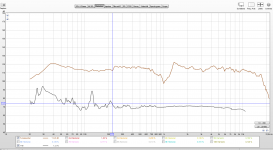
Above 500 Hz is not a big problem in my case.
Little bit more than 1% THD
Under 500 Hz it was horrible, see attached graph.
Would be nice to reach what is mentioned in patent: 150 Hz- 20k Hz flat freq response, under 1% THD in entire range.
It may sounds good.
Dipole radiation, holographic sound stage, like good ESLs or Mr. Linkwitz systems. (Orion, Pluto etc.)
Without investing a lot to good factory speakers or transformer for diy ESL.
It is too good to be true.")
Little bit more than 1% THD
Under 500 Hz it was horrible, see attached graph.
Would be nice to reach what is mentioned in patent: 150 Hz- 20k Hz flat freq response, under 1% THD in entire range.
It may sounds good.
Dipole radiation, holographic sound stage, like good ESLs or Mr. Linkwitz systems. (Orion, Pluto etc.)
Without investing a lot to good factory speakers or transformer for diy ESL.
It is too good to be true.
Attachments
To be honest I do not have real measuring mic too.
I use Panasonic WM61 capsule (3-4 $), connected to a modified USB sound card mi input. (CM6206 chip, new one around 10 $, I bought 2nd hand 4$)
Changed the coupling capacitors to higher value to have flat low freq. originally it starts to drop at 50 Hz.
I used it for my sub level adjustment and DRC at low freq. (measure with REW, create filters, export filter to convolver, play music with computer connected to HDMI digital amp with TI equibit chips)
Then I recognized it is quite accurate in the entire audio range.
I can measure my headphone up to 19.5 kHz
Even it is not a real calibrated instrument, can provide sufficient results.
Attachments
Hi,
I step forward with resonance and distortion problem.
Both of my prototype diaphragm (Canson paper and Xerox never tear) had similar behavior.
Resonate one low freq, and there is a big distortion on that frequency and a multiplication of it.
After try several things without real success I read again the patent US4903308 and implement solutions mentioned there.
The Canson paper distortion almost disappear and Xerox (more floppy material) improves a lot.
The phenomena and one solution is clearly written in the patent, and the described solutions works for me.
Wrine implement similar strips earlier.
I tried also with foam tape it was not working, fiber glass works.
I made a video of Xerox vibration (around 37Hz):
YouTube
"The present transducer as best seen in FIG. 1 will
have a resonant frequency dependent on the specific
transducer size and the material employed.As shown in
FIGS. 1 and 5, parallel strips of damping tape 73 are
adhered at predetermined locations on the inside of
each web end portion 24a, 24b, 26a and 26b. The strips
of tape, preferably made of a woven fiberglass such as is
found in strapping tape, aids in flattening the amplitude
response and reduces harmonic distortion resulting
from the device’s resonant frequency and its multiples.
Best results have been obtained with a damping tape
mass of about g of the mass of the diaphragm 22, divided
into strips spaced equidistantly apart from near the end
of each web portion to the edge of the central dia
phragm expanse. While three parallel damping strips
are shown, it will be appreciated that an increased num
ber of parallel damping strips spaced equidistantly but
closer together also works well."
Other thing is the damping of "elastomeric cords":
"The length of cord on each side of the expanse as indicated
at 65 in FIG. 2 determines the low frequency below
which the frequency response of the diaphragm is atten
uated. Such attenuation is desirable because the lower
frequency response in a diaphragm has a greater ampli
tude and must be attenuated to improve the overall
response. It has been determined that a cord length of 1;
inch, with the cord fastened l inch away from each side
of the expanse, satisfactorily attenuates frequencies
below 100 Hz."
you can see in the video the paper acts weird down low. it flaps around and does not follow signal very well
ofc 37 hz is low of course but this happens higher up as well. to get lower best results i got was either going heavy. or add that thick foam window tape. that 4mm thick pvc stuff. but still it is in no way perfect. i got better results when i made the round parts out of bended and coated foam bord. while the middle part remaind a rubanoide coil former thing YouTube
YouTube
Do note heavy eq used i believe. but not the weird wobbly paper thing going on. eq used is in the video or description
Last edited:
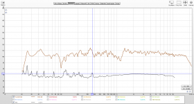
Your double winding solution seems has under 1% THD from 800 Hz till 5 kHz.
Outside more.
I'm still wondering how to reach the mentioned under 1% distortion in entire range.
Tedlar membrane with fiberglass strips, 36 awg silver wire.
That's the secret? (or under 1% THD in entire 150Hz-20 kHz range is not true)
I hope Sergiu can measure soon again to see what distortion level he reached with Canson, alu coils, and special cuts.
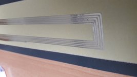
I get first trial of alu tape coils cut with vinyl knife on DIY cnc machine.
Unfortunately it is useless because only a small part is ok, at least something and I hope he can cut it perfectly.
Outside more.
I'm still wondering how to reach the mentioned under 1% distortion in entire range.
Tedlar membrane with fiberglass strips, 36 awg silver wire.
That's the secret? (or under 1% THD in entire 150Hz-20 kHz range is not true)
I hope Sergiu can measure soon again to see what distortion level he reached with Canson, alu coils, and special cuts.
I get first trial of alu tape coils cut with vinyl knife on DIY cnc machine.
Unfortunately it is useless because only a small part is ok, at least something and I hope he can cut it perfectly.
Attachments
Your double winding solution seems has under 1% THD from 800 Hz till 5 kHz.
Outside more.
I'm still wondering how to reach the mentioned under 1% distortion in entire range.
Tedlar membrane with fiberglass strips, 36 awg silver wire.
That's the secret? (or under 1% THD in entire 150Hz-20 kHz range is not true)
I hope Sergiu can measure soon again to see what distortion level he reached with Canson, alu coils, and special cuts.
I get first trial of alu tape coils cut with vinyl knife on DIY cnc machine.
Unfortunately it is useless because only a small part is ok, at least something and I hope he can cut it perfectly.
i am pretty sure it is not true, since not one measurement was posted EVER, of a comercial ruba. also dispersion patern or polar plot sucks, never posted either but it is the truth. by the way silver wire >? why would anyone use that. besides being expensive it does not do a whole lot. alumnium would make more sence
one other thing you mic has to be able to even measure that low distortion. the Panasonic is as good as the noise floor to do so
i had a umik and it llooked really flat in distortion but it was purely because it could not resolve lower distortion.
Last edited:
Silver wire I read in patent US4903308.pdf. I do not know why it is good.
Maybe it works like the foam on rubber and fiberglass tape.
Mean time I made some progress.
Made 3rd diaphragm and assembly today:
Canson 125g/m2 with 0.17 diameter copper wire coil.
I put 4 fiber glass tape stripes on each wing.
It is the 1st rubanoid where I can enjoy the sound what is coming out!
I will put more tape later try to dump the resonance at 120 Hz.
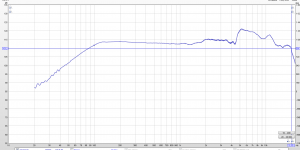
It goes up to 17 kHz. Distortion is not that bad this time.(see close field measurement)
I upload 2 videos, playing with my DIY closed box sub crossed at 80 Hz.
Without equalization.
I start to trust, it is not waste of time to play with it.

Video1
Video2
Maybe it works like the foam on rubber and fiberglass tape.
Mean time I made some progress.
Made 3rd diaphragm and assembly today:
Canson 125g/m2 with 0.17 diameter copper wire coil.
I put 4 fiber glass tape stripes on each wing.
It is the 1st rubanoid where I can enjoy the sound what is coming out!
I will put more tape later try to dump the resonance at 120 Hz.
It goes up to 17 kHz. Distortion is not that bad this time.(see close field measurement)
I upload 2 videos, playing with my DIY closed box sub crossed at 80 Hz.
Without equalization.
I start to trust, it is not waste of time to play with it.
Video1
Video2
Attachments
Silver wire I read in patent US4903308.pdf. I do not know why it is good.
Maybe it works like the foam on rubber and fiberglass tape.
Mean time I made some progress.
Made 3rd diaphragm and assembly today:
Canson 125g/m2 with 0.17 diameter copper wire coil.
I put 4 fiber glass tape stripes on each wing.
It is the 1st rubanoid where I can enjoy the sound what is coming out!
I will put more tape later try to dump the resonance at 120 Hz.
It goes up to 17 kHz. Distortion is not that bad this time.(see close field measurement)
Hello,
The choice of silver is due to its good behavior to corrosion and oxydation. But, if the copper is completely enclosed after gluing it, it will do the job as well...
This driver needs attention on three main sectors :
Firstly, the centering of the coil in the double magnetic gap is very important. If there are variations during the movement of the coil, this will induce distorsions. It's thus of prime to find an elegant way to maintain centered the coil in the gap all the time, while keeping its free displacement... Not an easy task ! Most of the used methods aren't effective !
Secondly, the material and the final constraint of the webs are of paramount importance. Since the humidity changes will obviously modify the specs of paper and, thus, the sound, "simple" paper is here the worse solution. The freedom of the webs, both up and down, at the two sides, will induce quickly an erratic movement of these edges, as soon as the audio power into the coil will be large enough... The resulting distorsion will then be very high ! Thus the constraint, i. e. the form of the webs, and their "termination" (up, down and on the sides) must be studied to avoid this erratic behavior for high input levels.
Thirdly, the whole weight of the complex "coil+webs" have to remain as low as possible, otherwise the impulse response, as well as the frequency response, of the system will be poor. Thus, the intrinsic rigidity have to be obtained with a compromise in mind !...
Hope this helps...
Best.
Last edited:
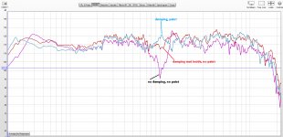
I play further with ruba.
1. Place damping inside (air filter cloth what I have home)
It has big effect around 1kHz (see close field measurements)
2.Try to paint the membrane, I was looking for "flexible" paint. I found in local shop Body 950 stone chipping protection for cars http://hbbody.com.gr/products/filesUploads/710_950 ANTICHIP_710_tds.pdf
The application of this material is far from perfect (ugly), because the diaphragm was already assembled and because I'm unexperienced in spray painting.
I was surprised how heavy it is, I almost double the diaphragm weight. (86 g)
I was expecting it kills the highs totally, but surprisingly the effect is not that much for highs.
It sounds less "paper", less shouting, subjectively.
Unfortunately I have no an-echoic chamber for measurement, and since it has dipole radiation the measurement strongly effected with room reflections. (I plan to make "an-echoic" measurements outside in my garden when the weather became better.)
I play with measurement in different positions, and seems as I have less resonation/distortion at lower freqs, I measures closer to theoretical "open baffle" freq response.
I was looking again to Mr. Linkwitz's site.
He was developing many dipole speaker systems.
Unfortunately I not heard any of the system, but there are too many review which tells his systems has extraordinary life-like sound.
Electro-acoustic models
What is the right baffle size, design for ruba?
Equalization to get proper low mid response?
Attachments
Well hello Borzi, i'm glad that another person is on our tracks... and i'm glad that another person came to my conclusion as well. Now if you want to experiment more with laq, apply paper tape vertically on the midle of the cils, +max 2cm further from the axe of each cil (cilinder) to the inactive edge and try to spray laq as thin as you can. Then take the paper tape down, let it completely dry for 10-12 hours than listen and post your impressions again... Thats the spot that should be treated this way. My ideea with the laq is to improve the perceived hight freq responce so you should never have to use a tweeter and to savour those airy hights coming from that huge membrane even more. You should try the cuts, oh boy what a joy.
The cuts not only 'improve' the hights but also tames the shouts.
The cuts not only 'improve' the hights but also tames the shouts.
Last edited:
The ideea behind the cuts, as i see it, is that they lower the central portion overall mass, but they act as an open door for the sound comming from the core of the paper itself letting it to come out..
You cannot escape that huge dip that you have there (that is the spot wich shows that this transducer has a behaviour similar to a clasic fullrange speaker with wizer... You know what i mean!) you can only tame it abit to a degree, but be carefull because everything must be a compromise in this speaker.. If you use too thick elasticks, and tension the, too much, you will gain better centering and lower resonances, and will improve its lets call it "STOP effect" (in simphonic music in those passages where all the instruments stops at the same time instantaneusly, the speaker will be really fast at this chapter) but you attain fewer microdetails and restrained voices, and using too thin elastics and not well tensionned correctly the membrane will be woobeling around.. All these tiny aspects has to be fine tuned just right because, you can go into the wrong ballpark..
Also ataining bellow 1% distorsion figures, IF someone can achieve this thing in fullrange may lead to an ordinary speaker like sound... I have searched bellow 1% from 150hz to 24khz with all the tricks that i know applied, and didnt like the classic sound. The dispersion remained, but the rest not....
I'm really curious to measure my speakers this week. These where finelly tunned to what i liked and not dist figures.
Ps: just a hint for the usage of laq, is that you should apply it before making the coil itself, and the cuts, and after this do the coil, then bond, then cuts, then cil interior treatment, then the back of the coil treatment and so on. And the laq should be applyied with a animal thin hair brush, but very thin so that the membrane will not be penetrated by the laq. Its much uniform applied this way, much easier and effective. Congrats for the builds, i love them both, Olegs, and yours.
Cheers
Sergiu
Between the foil (wich achieved the lowest dist from my point of view) and paper, i will choose paper at any hour to keep this speaker's distinct mid sound signature, airy hights, and disperion.. and Olegs and Wrines cottone paper is very appealing to me. Will be interesting to see silk or washy..
I liked rubas foil membrane only when i heard it playing as a tweeter. It is a nice improvement instead of a small ribbon with the impedance adapter trafo..
I liked rubas foil membrane only when i heard it playing as a tweeter. It is a nice improvement instead of a small ribbon with the impedance adapter trafo..
- Home
- Loudspeakers
- Planars & Exotics
- A DIY Ribbon Speaker of a different Kind