could you elaborate farther please?
not sure that I know where you are comming from or going to with this question. We were talking about flat planar diaphragms of solid plastic film or of woven fiber. What boundary reflection in particular are you referring to? With a RS style tweeter a woven fabric mesh diaphragm rather than a solid plastic film will loose far more energy within the diaphragm so there will be less energy at the diaphragm edses to get into trouble than there would be with a solid film. You will have to help me to get onto the page you want. Regards.
not sure that I know where you are comming from or going to with this question. We were talking about flat planar diaphragms of solid plastic film or of woven fiber. What boundary reflection in particular are you referring to? With a RS style tweeter a woven fabric mesh diaphragm rather than a solid plastic film will loose far more energy within the diaphragm so there will be less energy at the diaphragm edses to get into trouble than there would be with a solid film. You will have to help me to get onto the page you want. Regards.
I mean going in the direction of distributed mode loudspeakers: fight resonances not by damping the wave but by spreading the wavefront in order to get so many modes that you don´t see the forest because of that many trees.
edit:
Graphite has an enormous difference in the wave speed axial to the rings vs. other direction. Graphite foil consists of expanded (isotropic)graphite crystals with random orientation of the crystals in relation to their neighbours.
edit:
Graphite has an enormous difference in the wave speed axial to the rings vs. other direction. Graphite foil consists of expanded (isotropic)graphite crystals with random orientation of the crystals in relation to their neighbours.
so we are discussing different designs now?
if we are talking a large tensioned diaphragm with multiple drivers you still need to dissipate energy in the diaphragm. A stiffer diaphragm or a tighter diaphragm (putting aside the increase in overall resonant mode) will spread energy faster and farther but when the energy hits the frame it will reflect back just as fast and almost as far so then you will have distructive interference as well as nodal points. If you do not design in some kind of loss in the diaphragm and the frame then you will have problems with any kind of a controled dispersion pattern. Also a diaphragm that generated hemispherical wavefronts will get the ceiling and the floor into the picture and you don't want that so it is better to only have to deal with horizontal modes. What is it that you are thinking of doing? I am not sure that I follow where you are going with this. We had a hard time figuring out how to control just one diaphragm drive I am not sure that I would recommend anyone attempt to try and juggle multiple drivers. With all their money and thinkers the big boys have not much to show for their trouble following that path for the last twenty years and tens of millions spent. What's wrong with a straight ahead good old simple ESL? Use a dynamic driver to make the bass and you are off to the races.
if we are talking a large tensioned diaphragm with multiple drivers you still need to dissipate energy in the diaphragm. A stiffer diaphragm or a tighter diaphragm (putting aside the increase in overall resonant mode) will spread energy faster and farther but when the energy hits the frame it will reflect back just as fast and almost as far so then you will have distructive interference as well as nodal points. If you do not design in some kind of loss in the diaphragm and the frame then you will have problems with any kind of a controled dispersion pattern. Also a diaphragm that generated hemispherical wavefronts will get the ceiling and the floor into the picture and you don't want that so it is better to only have to deal with horizontal modes. What is it that you are thinking of doing? I am not sure that I follow where you are going with this. We had a hard time figuring out how to control just one diaphragm drive I am not sure that I would recommend anyone attempt to try and juggle multiple drivers. With all their money and thinkers the big boys have not much to show for their trouble following that path for the last twenty years and tens of millions spent. What's wrong with a straight ahead good old simple ESL? Use a dynamic driver to make the bass and you are off to the races.
Sorry, language problem. When I wrote spread the wavefront I meant break up the wavefront. See the foil as nodes that represent the expanded crystals and delays of different length connecting the nodes. The result would be that the plane rectangular foil in fact emulates a much more complex structure that hopefully has much more irregularly distributed modes.
I am still not clear here....
if we are discussing a linaeum style driver or a flat tensioned diaphragm with multiple drive points? Regarding your point of having a multiple of tiny nodes evenly distributed I thinkt that while the overall effect is to make the resonances less prominent when compared to several larger resonances in the end I believe that you just have more smear over more of the band that way. The goal should be for none anywhere rather than some everywhere. I just don't see that as a winning method. Perhaps you might just PM me as I don't think that this line of discussion really takes this thread anywhere. I am still not clear as to what you are talking about and where you are going with tihis. Regards.
if we are discussing a linaeum style driver or a flat tensioned diaphragm with multiple drive points? Regarding your point of having a multiple of tiny nodes evenly distributed I thinkt that while the overall effect is to make the resonances less prominent when compared to several larger resonances in the end I believe that you just have more smear over more of the band that way. The goal should be for none anywhere rather than some everywhere. I just don't see that as a winning method. Perhaps you might just PM me as I don't think that this line of discussion really takes this thread anywhere. I am still not clear as to what you are talking about and where you are going with tihis. Regards.
No problem, I think I will try an aero-like speaker with graphite foil anyway, but with a very different motor. If you look in the "motor based planar speaker" thread you can see that the balsawood smears the resonances perfectly above 2 kHz, and this despite the fact that the material has only slightly irregular structure with almost parallel running fibers. I don´t know the wave speed in graphite foil, but I think I have a good chance of getting far below 2kHz, also because I have less resonances of the structure as a whole.
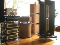
Not much usefull information, but anyway a nice look
http://www.audio-consulting.ch/?Products:Speaker
http://www.audio-consulting.ch/?Products:Speaker
Attachments

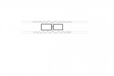
Maybe something like this
"Diaphragm" ? maybe just ordinary paper
But how about impedance ?
With foil fore "voice-coil" it will need a trafo
Maybe multiple thin copper wire could be used ?
Mechanical construction at both ends become slightly difficult
"Diaphragm" ? maybe just ordinary paper
But how about impedance ?
With foil fore "voice-coil" it will need a trafo
Maybe multiple thin copper wire could be used ?
Mechanical construction at both ends become slightly difficult
Attachments

a.wayne said:Hello Tinitus ,
The output energy , must be pretty low ...............................
I would think the opposite
As I mentioned earlier the magnetgap is much tighter than on an ordinary ribbon or planar
I beleive thats the main benefit from this priciple
But you may have a point in the sense that diaphragm weight probably is higher, which drags sensitivity down again
Im really tempted to build a proto, only way to find out

Several important issues are in favour of the Rubanoide
Low cost, due to less magnets needed
Opens possibility to use high quality N45-52
Tight magnet gap, with possibly higher sensitivity and good control
Simple diaphragm with no rattling issues
Easily done diaphragm, yet solid construction
Relatively small size, but still good displacement
Linear Xmax with underhung design
Easy to make bigger by just adding another unit
Supposed to sound better than planars
Negative ? ... I havent found any
I think I will give it a try
Anyone have an idea of exactly what the motor structure is inside of the Rubanoide?
They are positioning it as "not just another ribbon loudspeaker" but is the design close to a ribbon?
They are claiming a "resistive" load (flat impedance) across the usable bandwidth, and to me this implies no resonance, and no moving mass.
Is the magnet structure like a ribbon, but more closely spaced, like a voice coil gap? This could work with a flat voice "coil" - this would be like a ribbon, but with a stack of ribbon elements (just wires here) all coupled to the radiating surfaces.
I had several Lineaum tweeters of the RS/RCA type - but assumed they were just gimmicks - a weird radiating surface likely driven by piezo transducers.
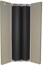
http://www.audio-consulting.ch/?Products:Speaker:Rubanoide
These, however, are claiming a frequency response of 100Hz to 20kHz.
So, anyone know what these are like on the inside?
Any ideas what they are doing with the backwave? They appear to be dipoles, but each side looks like it would have its own backwave, or some cavity resonance between the front and back radiating surfaces.
They are positioning it as "not just another ribbon loudspeaker" but is the design close to a ribbon?
They are claiming a "resistive" load (flat impedance) across the usable bandwidth, and to me this implies no resonance, and no moving mass.
Is the magnet structure like a ribbon, but more closely spaced, like a voice coil gap? This could work with a flat voice "coil" - this would be like a ribbon, but with a stack of ribbon elements (just wires here) all coupled to the radiating surfaces.
I had several Lineaum tweeters of the RS/RCA type - but assumed they were just gimmicks - a weird radiating surface likely driven by piezo transducers.
http://www.audio-consulting.ch/?Products:Speaker:Rubanoide
These, however, are claiming a frequency response of 100Hz to 20kHz.
An externally hosted image should be here but it was not working when we last tested it.
So, anyone know what these are like on the inside?
Any ideas what they are doing with the backwave? They appear to be dipoles, but each side looks like it would have its own backwave, or some cavity resonance between the front and back radiating surfaces.
neededandwanted said:Anyone have an idea of exactly what the motor structure is inside of the Rubanoide?
Yes, forunately there are no secrets around it
All you need to know to build one is there
But no details about size and construction of "voicecoil"
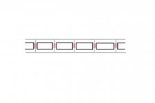
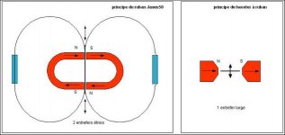
But "motor" design consist of two opposite oriented, which is convenient fore "wire-layout"
AudioConsulting may use a few tricks of which we dont know anything
http://home.tele2.fr/mon-site-perso/ menu at the bottom, with more information
No doubt, some experience with DIY ribbons will be an advantage, or othervise it may all look quite strange
A solid and precise mechanical design and build will be very important, and the most difficult part
Some sort of possible adjustment of magnetgap might be benefitial
Attachments
tinitus said:Yes, forunately there are no secrets around it
All you need to know to build one is there
http://home.tele2.fr/mon-site-perso/ menu at the bottom, with more information
When I click on that "construction" link at the bottom of that page, it appears that "no secrets" is not what the author has in mind.
It says there (in French):
"I have decided to protect my invention." (and paraphrasing heavily) "Send me a check for 200 Euro and I'll send you a key to get to the secure documentation about how to make one."
I like your picture better, tinman.
I could actually design from that. And an adjustable gap sounds like the way to go with this completely.
I would probably cheat the big horseshoe sections and use two bars and a piece of steel to complete the circuit on each side.
I am now assuming the flat coil has the conductors go down the front and up the back, so that the entire coil and membrane acts together as a single dipole arrangement (since the gap in the back has reversed polarity from the gap in the front).
- Home
- Loudspeakers
- Planars & Exotics
- A DIY Ribbon Speaker of a different Kind