A high resistance diaphragm is used for ESLs to maintain "constant charge" operation. By having a very high resistance, the charge on the diaphragm is prevented from moving toward the center of the diaphragm when the diaphragm is deflected toward one stator or the other by the audio signal.
If the charge were allowed to move (low sheet resistance diaphragm), at extremes of excursion all the charge would move to the center of the diaphragm so only the central area of the diaphragm would be driven and the result would be distortion.
I believe Martin-Logan uses a vacuum deposition process to put an extremely thin metallic coating on the diaphragm. Whatever the method used, it is a very high resistance coating.
MR
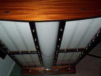
MRehorst said:No, it's not one of the Quad 57s. Not an ESL63 either. Could be one of the newer models (I haven't seen their guts), or someone else's speaker altogether.
The newer models are close enuff to the 63 that you'd recognize a family resemblance, so these are another maker. I assume the damped part in the middle are tweeter panels?
dave
Graphite
Over the years graphite has been the conductive coating of choice for many ESL makers. Graphite it a poor choice for everyone but the makers, guaranteeing a 100% failure rate. High voltage on the system will eventually drive the carbon (graphite) off as carbon dioxide.
Cyclotronguy
Over the years graphite has been the conductive coating of choice for many ESL makers. Graphite it a poor choice for everyone but the makers, guaranteeing a 100% failure rate. High voltage on the system will eventually drive the carbon (graphite) off as carbon dioxide.
Cyclotronguy
Eventually like when? I am still waiting on drivers I built 12 years ago to stop working.
No I haven't had them biased continuously for 12 years, but the force produced by the electric fields in the speakers is very weak compared to the force used to rub the graphite into the film.
The graphite coating will outlast foam speaker surrounds, belts and lubricants used in tape machines, esoteric CD players, and turntables. It will outlast most pots, many switches, most electrolytic capacitors, vacuum tubes, and a lot of other materials found in audio systems.
Graphite works just fine and lasts a long, long time.
MR
graphite coating
Yes,cyclotronguy is right - I had the stators on my Martin Logan CLS's replaced twice. Once was for delamination, and the other time was most likely due to the carbon issue. That is why ML went to the molecular deposition process (incidently, this is done for them by PPG corporation, using the same process used to deposit heating films onto aircraft winshields, for anti-icing protection).
It is also tricky to achieve a uniform resistance using carbon, since it is not a controllable process - it is easy to end up with more carbon on one portion of the diaphragm.
Sorry, I no longer have access to the documentation; it belongs to my previous employeer.
Part of their normal operation required frequent fabrication of high purity carbon into electrostatic deflectors. The carbon and documentation came from a small branch of Union Oil that supplied the carbon in various forms.
Rate of re-dox was a time, charge, pressure, mole relationship; proportional to time and charge, inverse for pressure.
peterr said:I remember seeing this picture before somewhere...
As far as I remember it is a diy project using the panels of two Quad esl57 speakers per side.
That could well be it -- stacked quads done right. I only have a non-captive tweeter panel, but the style is definitly the same.
dave
As an amusing side note, Wuti Larn, then of Landec Labs in
Menlo park, worked with ML originally and recommended
a good coating, but they chose to go with the graphite.
The result was a 100% failure rate after some years. It
is a tribute, however, to Gayle Sander's astute marketing
that this issue never became public due to his very
generous replacement policies.
I have seen photos of ML's assembly techniques in some of their sales brochures. One of the things that jumped out at me was the use of what appeared to be polyfoam tape, sticky on both sides, used to support the diaphragm (the horizontal strips you see every few inches). Does anyone know if that is actually what they use? That tape is an absolute disaster- it usually dries out and crumbles within a year or so of application.
Maybe they didn't worry about the diaphragm because they knew other things would fail long before the diaphragm...
MR
Maybe they didn't worry about the diaphragm because they knew other things would fail long before the diaphragm...
MR
Yes, they use a high-density foam tape, both for the horizontal supports, as well as the edges of the panesl. The construction is:
metal stator|double sided adhesive foam tape|mylar diaphragm|double sided adhesive foam tape|metal stator
On my CLS's, the foam core of split due the stresses imposed by the panel curvature - this did not really affect sound quality significantly, but it makes you question their design practices.
In spite of all that, the CLS is a superb speaker.
Hi on the topic of ESL's I have a few questions if anyone would care to help.
Firstly, with high/low resistance diaphragms 'gilid' mentioned 100Kohm resistance. Now I have been following this page regardin ESL's, http://www.amasci.com/esloud/eslhwto.html, and they say also 100Kohms, but make note that the resistance is measured using two pennies placed on the film a few inches apart, and then using a digi-multimeter. Would commercial speakers be around that or do they measure resistance differentl? Also is it bad to have too much resistance, say, 400Kohms or 1Mohm even? Or would you just have to bump up the bias suppies power? If that is the case, why not just use a high condutive material for the diaphragm and use a low power bias supply? (I am no electronics/physics genius so please excuse my questions if they aren't logical)
Regarding the semi-conductive coatings also, I did a bit of research on conductive inks and came up with this page
http://www.conductivecompounds.com/products.html
Down the bottom they have the C-100 product which is a resistive ink and when mixed with the AG-500 product (a conductive ink) you just balance it out to get the specific resistance/conductivity required. They even say it can be used for audio speakers, which I assume they mean ESL's. Has anyone heard of using this method of conductive inks or done it themselves? If so what kinda success if any was had?
Last question, ESL amplifiers. Are they different than an ordinary amplifier or is it just market hype?
The actual film resistance is not very critical, as long as it is high (>100K) A lower resistance would cause the charge density to shift around over the surface of the diaphragm, leading to uneven performance, and stress on the psu.
I do not know how various manufacturers measure it, but the penny technique sounds reasonable.
The ink idea sounds good - the best way to find out if it works is to try it!
Regarding ESL amps, yes, they are very different from standard amps. A true ESL amp will drive the ESL panel directly, negating the need for the ESL powersupply. Such an amp needs to produce an output voltage in the range of several 1000's of volts (as opposed to 20-40 volts for a standard amp). They tend to be complicated, expensive and dangerous, so not too many companies actually make them. A company called 'Beveridge' used to make such an amp. I never had the chance to hear one, but they are supposed to be great - you eliminate a lot of components in the signal path.
specialx said:Hi on the topic of ESL's I have a few questions if anyone would care to help.
Firstly, with high/low resistance diaphragms 'gilid' mentioned 100Kohm resistance. Now I have been following this page regardin ESL's, http://www.amasci.com/esloud/eslhwto.html, and they say also 100Kohms, but make note that the resistance is measured using two pennies placed on the film a few inches apart, and then using a digi-multimeter. Would commercial speakers be around that or do they measure resistance differentl? Also is it bad to have too much resistance, say, 400Kohms or 1Mohm even? Or would you just have to bump up the bias suppies power? If that is the case, why not just use a high condutive material for the diaphragm and use a low power bias supply? (I am no electronics/physics genius so please excuse my questions if they aren't logical)
-----
The bias charge on the diaphram has very little to do with the resistance. If you take a standard resistor and apply some voltage to one end, leaving the other end open, in a negligible time the other end will be at the same voltage. This is true for a 5 Ohm resistor and a 50 MegOhm resistor (if they go that high.) The high resistance of the diaphram coating, as has already been pointed out, is to prevent the charge from moving around a lot while the speaker is operating.
From a physics point of view, if you consider the stators alone, there is no electric field between them when the speaker is not playing. They are both at some high voltage relative to ground, but there is no net voltage between them, so the potential (Voltage) between them must be zero, and the electric field, which is the gradient of the potential (measures the rate of change in space) is perforce zero also. This also means that with no audio signal, the only thing holding the diaphram in place is the tension from the sides. Without that tension, the diaphram would be free to move anywhere between the stators. I'm ignoring edge effects in this model, but that's a very good approximation, because almost all of the active stuff of the speaker is in the bulk, and not on the edges.
The reason that there is a resistive coating on the diaphram is that it has to carry some charge, or the speaker wouldn't work. Think of this resistance as being a poor conductor. Now, the film itself is an insulator, so you couldn't really store much charge in a uniform way on it. Personally, I don't think that the resistive film needs to be very even. Any conductor, even a resistive one, will have any electric charge that is on it evenly distributed around a uniform surface. Corners will get charge concentration because of boundary effects, but a flat resistive sheet will have an almost completely uniform charge density on it, even if there are inhomogenities in the resistance. This is all for static situations; I haven't pondered the deeper ramifications of the speaker while it is playing.
Regards,
aeronaut
That's Wayne Piquet's work on Quads. He rebuilds them (after bombarding me with lots of questions to learn how). He's into different frames and lots of finish changes. Not my cup of tea, but style is subjective.
As to diaphragm resistance, most if not all modern ESL's charge the diaphragm through a high value resistor (10 - 100 megohms). This resistor is really responsible for maintaining constant charge operation of the panel. The panel resistance is measured in ohms per square. Square what? Exactly.") It's non dimensionalized, and the two penny technique is good to test to make sure your diaphragm is conductive, but not really useful to reporting an actual meaningful surface conductivity value unless you factor in the penny geometry.
It's non dimensionalized, and the two penny technique is good to test to make sure your diaphragm is conductive, but not really useful to reporting an actual meaningful surface conductivity value unless you factor in the penny geometry.
Simplification alert:
You can think of the resistance as part of an RC network of sorts. you want the time constant of the charge movement to be slower than the lowest frequency you want to reproduce for linear operation of the cell. so you could get away with a lot more conductive diaphragm in a tweeter than a bass panel.
As to foam tape, there are a lot of different grades out there. The eurathane foam with acrylic adhesive seems to hold up a lot better than the cheap grade foams. Your friends at 3M have a lot to say about foam tapes.
As to graphite: It's hard to get a more inert material to coat a diaphragm with than carbon. Back in my pupal stages, I used to use graphite to coat ESL diaphragms. It works well and lasts a long time in my experience (that CO2 argument strikes me as implausible). But it's tedious and tiring to apply and you can easily rip thinner diaphragm materials. There are easier to apply coatings whose surface resistivity can be tailored to whatever value you want. I use about 10^11 ohms/sq for quad ESL57 rebuilds, and about 10^8 ohms/sq for DIY esl cells and ESL63 rebuilds.
As to diaphragm resistance, most if not all modern ESL's charge the diaphragm through a high value resistor (10 - 100 megohms). This resistor is really responsible for maintaining constant charge operation of the panel. The panel resistance is measured in ohms per square. Square what? Exactly.
It's non dimensionalized, and the two penny technique is good to test to make sure your diaphragm is conductive, but not really useful to reporting an actual meaningful surface conductivity value unless you factor in the penny geometry. Simplification alert:
You can think of the resistance as part of an RC network of sorts. you want the time constant of the charge movement to be slower than the lowest frequency you want to reproduce for linear operation of the cell. so you could get away with a lot more conductive diaphragm in a tweeter than a bass panel.
As to foam tape, there are a lot of different grades out there. The eurathane foam with acrylic adhesive seems to hold up a lot better than the cheap grade foams. Your friends at 3M have a lot to say about foam tapes.
As to graphite: It's hard to get a more inert material to coat a diaphragm with than carbon. Back in my pupal stages, I used to use graphite to coat ESL diaphragms. It works well and lasts a long time in my experience (that CO2 argument strikes me as implausible). But it's tedious and tiring to apply and you can easily rip thinner diaphragm materials. There are easier to apply coatings whose surface resistivity can be tailored to whatever value you want. I use about 10^11 ohms/sq for quad ESL57 rebuilds, and about 10^8 ohms/sq for DIY esl cells and ESL63 rebuilds.
- Status
- This old topic is closed. If you want to reopen this topic, contact a moderator using the "Report Post" button.
- Home
- Loudspeakers
- Planars & Exotics
- Electrostatic speakers, real ones and...Martin Logan