Would it be difficult to design a tube amp that just outputs a high-RMS signal, with low distortion (no output transformer)? (I don't think so ") )
)
If so, would it be nessecary charge the stators instead of the diaphragm, and drive the diaphragm instead to avoid having to produce two signals 180 degrees out of phase?
)If so, would it be nessecary charge the stators instead of the diaphragm, and drive the diaphragm instead to avoid having to produce two signals 180 degrees out of phase?
What is difficult?
Probably harder than a chip amp for sure.
Certainly potentially dangerous - I have repaired such a beast - the only audio power amp I've ever worked on that had a skull and cross bones warning symbol
No you would not want to drive the diaphragm, charge migration ... unstable ... diaphragm sticks to sators ... arcing ... not enough space here to explain. May I humbly suggest reading up on some theory, maybe someone else will have some good links, just remember not all you read is correct! Walker's (Quad) patent(s) is/are a good read.
I've wanted to do this for years, but some how something always came first. And of course I'm not sure I want to modify my 63s, so that means building some panels first.
It's a hard problem. And mistakes are spectacular, potentially dangerous, and always expensive. I've built a d-d ESL amp that is a scaled-down (900V) version of the 5kV monster that I really need (and which just awaits more available money, hah hah). But even that scaled-down one was a real ****** to stabilize.
I definately don't have the experience to do this. I think I'll stick with a transformer
Bigwill,
I've build one with a 4.8kV supply.
It's definately the most dangerous, read deadly, and tough tubeamp I ever built.
You must be very experienced with tubes and voltages above 1kV to make this happen, so like you said if you don't have the experience don't even think of trying.
What you can do is try to find an Acoustat X amp and replace the sand for tubes. Still very dangerous though.
Dick.
I've been wondering the same thing lately. I've seen a diy direct drive esl amplifier on the net. Can't find the link at the moment, will check for it later.Bigwill writes:Would it be difficult to design a tube amp that just outputs a high-RMS signal, with low distortion (no output transformer)?
I would like to try building a push pull tube amp to drive a pair of diy esl's. I'm thinking it would need transformers, though. I'm not feeling comfortable working on an amp with a 4-5KV power supply.
Just a rough idea would be a pp amp with a +- 200v power supply with a 1:5 step up transformer. The transformer probably isn't an off-the-shelf part, so I've been searching the net for transformer winding info.
I'm quite rusty at tube circuit design, haven't worked with them in about 30 years, so the whole thing is just an idea at the moment. Sy-feel free to correct me if I'm going down the wrong path.
The step-up may work, but again, the hard part will be stabilizing it- reactive loads are difficult.
Would it need more stabilization than a traditional esl setup of a tube amp driving an 8 ohm step down transformer, in turn driving a voltage step up transformer to the esl's?
My direct-drive amp for the Quad ESL-63 (long)
(I've copied a posting I made to Audio Asylum on this subject, especially about driving the Quads, here
It’s not easy and it is incredibly dangerous. But of you’re determined and experienced with the hazards of very high voltage electronics, it can be done. I built a direct drive amp for Quad ESL-63s (and with other ESL projects in mind) and in the process gained some insight into the unique drive requirements of the Quads. To drive them to anywhere near full output levels requires a lot of voltage, even more than for many other ESLs, because the Quad uses a fairly high impedance panel design for an ESL. This is evidenced by the step-up ratio of the pair of input transformers which is about 1:170 according to my measurements (at 1 KHz with the transformers in circuit). Most other ESL step-ups are in the 1:50 to 1:100 range. The bias voltage of 5.25KV is also on the high side. The 63 is specified for “programme peak for undistorted output” of 40V (corresponding to 28.3 Vrms or 100W into 8 ohms, at which level the speaker will output 106 dB SPL in the midrange, IIRC). If you do the math, that means that maximum drive at the secondary equates to 4800Vrms or 6800 V peak!
The next thought is that you don’t really need to drive the Quad to full specified power and that you can get by with less voltage. That’s the first reasonable compromise that you ought to make. Even so I wanted to go for the full Monty, if only as a challenge.
To pull this off, you’ll need very high voltage rated tubes, which probably means transmitter tubes and a very high voltage supply. You can choose among many types of transmitting tubes, although I prefer triodes for sound quality and the lower plate resistance which provides better coupling as the ESL’s impedance drops at high frequencies. You’ll disconnect the Quad’s trannies, and connect your new amp to drive the inputs of the Quad’s delay line circuit which is on the secondary side of the trannies. The protection circuitry is therefore disabled unless you wish to incorporate it somehow into the new amp design (I haven’t done so yet but probably will). Generally you’ll use a push-pull arrangement with large HV plate load power resistors to B+, the plates then connected to the Quads via HV caps. Or you can use choke loading, or use a push-pull transformer primary as a load without a speaker attached (but it will be hard to find a conventional transformer with enough voltage rating). All of these require compromises and I’m leaving out tons of details, of course. Morgan’s Jones’ book has a nicely conceived 845-based ESL amp design, although it might not make enough voltage for ESL-63s.
I haven’t mentioned my design yet because it’s so gargantuan, impractical and crazy that nobody in his right mind will want to duplicate it. I use four 833 transmitting triodes per channel (not a typo) which are run well below rated dissipation in a push-pull mu-follower bridge configuration to achieve enough current drive (ie: slew rate) for high voltage/high frequency testing of other ESL designs. The thing runs off of +/- 4000 volt supplies and uses a pentode servo amp to correct output DC levels. I run the upper cathodes directly into the Quads without coupling caps (kids, don’t try this at home). It will deliver more than 4800 Vrms to the Quads at full tilt. How does it sound? Well, pretty damned good to my ears. The Quads now sound leaner, tighter and airier, all of which were needed improvements IMO. Detail is astonishing in a very natural way, as is punch and “sock”. Was it worth the effort? For me, yes, but then I enjoyed the journey. Now I still have final packaging ahead of me.
Well, not quite, but very nearly so. My prior situation was a separate dedicated listening room, no kids, a wife who knows what to stay away from and cats who aren't allowed in the room. But all that changed with two moves, two renovation projects, and two hurricanes. Everything is currently in storage awaiting time and space to continue. By the way, another aspect of insanity is that each channel dissipates a bit over 1000W at idle (class A and all), and I live in Florida, not Alaska. On our chilliest days, that’s more heat than we need for that room.
On a more serious note: If anyone is contemplating a high voltage project like this one or even one less potent, besides having sufficient HV experience, let me add one other piece of advice. I never tested the HV stages and power supplies alone. I always had a buddy watching and helping. Fortunately, like me, my friend is a keen audiophile and an amateur radio operator (many of whom are used to working on HV RF amps). We kept an eye on each other and forced each other to follow sometimes tedious safety procedures and check lists – like double-checking wiring, making sure caps were discharged, etc.
Another old rule makes sense whether the voltage is 40, 400 or 4000. That is to keep one hand in your pocket. Only reach toward a high voltage circuit with one hand. Keep the rest of your body away from the bench. If you should accidentally contact a live point, there is no (or less) circuit path for current to follow (oh, and wear rubber-sole shoes). A burnt finger is better than a stopped heart, I would think. I’m not saying this alone makes it safe to touch HV points, just adds a layer of safety. Avoid metal jewelry like big Rolexes dragging across power supply caps. If all this sounds too hard, please just stick with 6922s and EL34s and be careful with them too!
Two thoughts:
- for a directly coupled amp running an ESL you'll need EQ in the amp to get a flat response. If you look at the Acoustat X design (not a bad place to start) you'll find the EQ.
- One trick that has been published (Audio Amateur, iirc) is to use a standard tube amp and take your outputs from the plates of the tube, off the primary of the transformer, capacitively coupled is one possibility. You will need a resistor on the secondary, but it might suffice to use a relatively high resistance there (32 ohms?) too keep the transformer happy. You get less swing than you might with a transformer coupled interface, but it's a place to start.
If you used an amp that had something like 811s in the ouputs and 900volts on the plates, you'd have a swing of 1800volts which will likely drive most ESLs within 3-6dB of their max, so it might be fine.
_-_-bear
PS. not much point to think about using solid state devices, since the B+ voltages are pretty much out of the range of possibilities...
PPS... well, having said all that, if ur using a class AB or B amp then you might have a problem with the drive, since the stators want to be controlled with a voltage all the time... this leads us to the Class A situation, and as soon as you combine Class A and BIG high voltage tubes, you're talking A) derating the "output power" of the tubes as compared to the class B/AB case and B) lowering the B+ some and C) lot's-O-heat and power being "wasted"...
- for a directly coupled amp running an ESL you'll need EQ in the amp to get a flat response. If you look at the Acoustat X design (not a bad place to start) you'll find the EQ.
Bear, you are correct. I've tried mine without this EQ and you get way to many highs.
Also like Brian mentioned, the sound is leaner, tighter and airier.
Dick.
for a directly coupled amp running an ESL you'll need EQ in the amp to get a flat response. If you look at the Acoustat X design (not a bad place to start) you'll find the EQ.
For most panel ESLs this is quite true. As the wavelength shrinks compared to the panel dimensions, beaming causes a treble rise and something has to be done about that. At the bottom end you have to deal with the panel resonance(s) and dipole cancellation. These can be handled by low-level circuits before the direct drive amp, at least in theory.
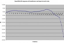
But the situation is different for the Quad ESL-63 and its newer relatives. Most of the frequency response shaping has been done in the panels themselves by adjusting annular ring dimensions and in the careful design of the delay lines which also act as low pass filters for the outer rings. Take a look at the attached response curve I measured from the input terminals to the transformer secondaries (which are also the inputs to the HV delay lines). This is NOT the Quad’s total response to the air – just what the input circuits (mainly the step-up transformers) are doing to the signal before the panels see it. While it is not perfectly flat, I wouldn’t characterize it as EQ either, or at least not much compared to what has to be done for regular panel systems. The response curve shows a rise broadly centered around 10 KHz, but then a rapid fall-off in the upper octave and beyond. The bass response extends smoothly down to infra-bass frequencies with just a gentle rise. These effects are audible in the stock speaker but correspond, in my opinion, to two slight weaknesses, minor as they are compared to most other speakers.
So you can just connect a direct drive amp to the delay lines without the need for any EQ. What you get (assuming the DD amps are flat, as mine are) is the removal of the attached response curve. In other words, the response at 10 KHz is reduced, but the upper octave and beyond is restored (think SACDs). Also, the bass is tightened a dB or two. I think both of these are improvements to the stock speaker. The treble is now very smooth and airy. The bass end has a welcome tightening, but full bass balance remains. For cleanest treble, I run my Quads “naked”, but that’s another story…
Attachments
You're assuming that the network going to the 63's panel provides a flat output for a flat input - I am not so sure of that. Any resistors or caps in the circuit? DCR from the coils?
According to Walker's teaching, the response you get is a function of the reactive impedance of the ESL vs. the source impedance of the thing driving it. You can match to different reactances vs. frequency and get a variation in output vs. bandwidth.
Thus the Strickland patent and the Audiostatic Euro patent which seek to provide two points of matching impedance from a nominally single source yielding a nominally flat, wide bandwidth result with reasonable efficiency.
At least that's how I recall it...
I'd expect that a given high impedance tube amp's direct drive output would work exactly the same way as a transformer coupled interface of the same impedance. But maybe with NFB, the ESL's response could be held flat?? Hmmmm... not sure about that.
_-_-bear
You're assuming that the network going to the 63's panel provides a flat output for a flat input - I am not so sure of that. Any resistors or caps in the circuit? DCR from the coils?
Not at all. The whole network is anything BUT flat.
In the case of stock Quads, think of there being two cascaded “black boxes”. The first box includes the input blocking capacitor, series resistors, the protection circuit and the step-up transformers including all the transformers’ leakage reactances and resistances in this one “black box”. The second black box has all the delay line impedances as well as the panels’ impedances factored into its input impedance. Where the first box connects to the second box is where I made the measurement shown in the chart, and also where I connect my DD amp. All the effects of the output impedance of box 1 interacting with the input impedance of box 2 are already captured in the chart response. So if you delete box 1 and replace it with a voltage source (the new DD amp) you will get a system response like the stock unit MINUS the response shown in the chart, no more and no less, because the impedances were already factored in. So the new system reduces the original 10 KHz bump, etc. And that’s exactly what did happen.
My original point was only that box 1 has mild effects on the response and really couldn’t be considered to have EQ like you might see in other ESLs. The significant shaping is done in Box 2 electrically and acoustically. This makes it possible to directly drive Box 2 with no EQ required in the amp.
According to Walker's teaching, the response you get is a function of the reactive impedance of the ESL vs. the source impedance of the thing driving it. You can match to different reactances vs. frequency and get a variation in output vs. bandwidth.
Of course, that's true for any networks in EE, not just because Walker said so. And the effect is contained in the chart.
I'd expect that a given high impedance tube amp's direct drive output would work exactly the same way as a transformer coupled interface of the same impedance. But maybe with NFB, the ESL's response could be held flat?? Hmmmm... not sure about that.
If you use triodes for the DD output stage the plate impedance can be pretty low relative to panel impedance, so the amp behaves like a voltage source for all but the highest frequencies. In my design, I used mu-stage bridge finals which have output impedances more like a cathode follower. The output Z of my DD amp is below 500 ohms. That may sound high, but hold on a minute. This is at the high voltage/high impedance side of the circuit. Since the Quads use a 1:170 step-up ratio, that equates to an impedance transformation ratio of almost 29,000. So 500 ohms is like 0.017 ohms source impedance in an amp driving the primary, which is a damping factor of over 450 at an 8 ohm reference. My point is simply that my DD amp, and probably many others triode DDs, can be considered a voltage source when directly connected to a high Z panel. That’s especially so for Quads since the delay lines block some of falling capacitive reactance at higher frequencies. By the way, you can add HV resistors in series between the DD amp and the delay line (or panels) to change the voicing.
ease
Hi,
the major Probs regarding a DD-ESL-Amp are the high voltages needed, the reactive, strongly varying impedance of the ESL and the enormous power You need for sufficient bandwidth.
Because of the fallig impedance of a capacitor, You´ll need some current to drive the ESL at higher freqs, i.e a lot of wattage. Additionally the amp has to work stable with highly capacitive loads.
Using high efficiency panels like MLs that don´t need much voltage to sing is the first way to a solution.
Simple triode amps can do the job then -when You´ve got the right tube, i.e a KR845 running on 2kV plate voltage and Class A. A triode with an active load (current source) will be better, especially with regard to higher load currents and greater bandwidth and linearity and low output impedance. Feedbackless amplification with exceptional good sound and dynamics is then possible
Using a good panel You only need to equalize the phase cancellation which is easily done with an active filter and which doesn´t stress the amp because of the low load currents in that frequency range.
Nearly all other concepts work with pentodes (Class B, or AB) and rely on heavy feedback and compensation to get the thing linear (Beveridge, Acoustat, AudioExclusiv). The sound of these devices is relatively poor with regard to cost and is imo no way better than using a good but much cheaper and safer trannie.
One of the biggest probs is to find the right power devices (e.g running a 6HB5 or PL509 on 5kV can´t be good, when the tube is rated for 700V continous plate voltage, even when 7kV pulses are allowed!) If You´re using triodes for the power stages the driver stages will be quite demanding, but highvoltage FETs could do the job.
There are just a very few special highvoltage transistors around that aren´t intended for these applications, so in most cases tubes do the job, but not normal audio tubes. You won´t find 5kV, 500mA babes in the standard audio department.
Another prob is to get a good and clean power supply. Best thing is probably to get one from those highvoltage companies, who sell supplies up to several hundred kV and kW.
The whole beast will work and sound deliciously good but it´ll cost! It´ll be rather inefficient! It´ll heat up the listening room!
It can be a very dangerous part to work with!
But what the h...
Yeah
Calvin
One of the biggest probs is to find the right power devices (e.g running a 6HB5 or PL509 on 5kV can´t be good, when the tube is rated for 700V continous plate voltage, even when 7kV pulses are allowed!)
The best approach in my view is not to think of audio tubes, but to think like a radio amateur and find high voltage RF transmitting tubes, of which there are many choices. Amateurs have been building 1KW plus RF power amps for decades. Borrowing a few tricks from those designs is useful.
I ended up selecting the 833 RF triode for my design. This is but one example of how a transmitting tube can be used for an ESL DD amp. The 833 was originally designed for RF amplifier duty up to 30MHz and also for audio amplification duty delivering as much as 2700 W in class B PP (for use in AM modulators). But the main rating of interest is the 4000 V DC plate maximum. When biased this way and used in typical service the plate can reach peaks of almost 8000 V. The 833 turns out to be quite linear too, and can be driven comfortably to full output with a 6SN7 driver stage. There are many other choices besides the 833, such as the 3-500Z or the 3-1000Z.
Another approach to high voltage devices is to stack tubes in a series arrangement so that all tubes evenly split the voltage between B+ and load, and the grids are on a resistor divider ladder. There are lots of implementation problems with this approach but it can be made to work. I toyed with this for a while before choosing the 833 for my design.
Nearly all other concepts work with pentodes (Class B, or AB) and rely on heavy feedback and compensation to get the thing linear (Beveridge, Acoustat, AudioExclusiv). The sound of these devices is relatively poor with regard to cost and is imo no way better than using a good but much cheaper and safer trannie.
Agreed. If that's the choice, stick with a good trannie.
Another prob is to get a good and clean power supply. Best thing is probably to get one from those highvoltage companies, who sell supplies up to several hundred kV and kW.
I wouldn’t advise going that route. It will be expensive and hard to find a unit with the right specs for your exact application. You can do better with DIY. It will be big and heavy, but not very hard to design or build. Much easier than the amp stages themselves. Again, start with well known ham radio approaches to power supplies for those big RF amps (buy an old copy of the Radio Amateur’s Handbook from ARRL at a flea market to see design ideas). The power transformer is the hardest purchase. I use a surplus trannie about the size of a car battery that came from an old Collins transmitter. By using series diodes in bridges and series filter caps you can rather easily make sturdy well filtered HV. In my case one trannie with twin CLC filters produces + and – 4000VDC. Ham fests or electronic swap meets are great places to get these kinds of parts for relatively cheap.
The whole beast will work and sound deliciously good but it´ll cost! It´ll be rather inefficient! It´ll heat up the listening room!
Right on!
At the moment if you drive your ESLs from a tube amplifier the amplifier output transformer secondary is connected to the ESL transformer primary. What would be involved in producing an output transformer to drive the ESLs. This would at least remove one transformer and would remove the necessity to operate the amp at very high voltages.
Stuart
Stuart
- Status
- This old topic is closed. If you want to reopen this topic, contact a moderator using the "Report Post" button.
- Home
- Loudspeakers
- Planars & Exotics
- Tube amp specifically for driving ESLs