Licron test
I checked the stove-black coated diaphragm today and found the surface conductivity beyond the capability of my DMM to read (i.e. it looked the same as the "noise" that makes the thing bounce around 0.00 nanosiemens).
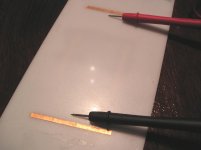
I also got a can of Licron and sprayed the new diaphragm with it. This was my first attempt to use the Licron- the spray leaves a pale grey coating with small spots. Here are photos of the panel before
spraying, and after.
The Licron appears to wet and stick to the polyester diaphragm just fine..
I masked off the corners to prevent leakage to gound via the corner screws per the original ESL-63 panel construction. I also masked off the rest of the driver to prevent the spray from going places where it shouldn't go.
The label on the Licron can says to let the stuff cure for 24 hours, so tomorrow afternoon I will check the resistivity and if it looks OK, I'll reassemble the speaker.
I_F
I checked the stove-black coated diaphragm today and found the surface conductivity beyond the capability of my DMM to read (i.e. it looked the same as the "noise" that makes the thing bounce around 0.00 nanosiemens).
I also got a can of Licron and sprayed the new diaphragm with it. This was my first attempt to use the Licron- the spray leaves a pale grey coating with small spots. Here are photos of the panel before
spraying, and after.
The Licron appears to wet and stick to the polyester diaphragm just fine..
I masked off the corners to prevent leakage to gound via the corner screws per the original ESL-63 panel construction. I also masked off the rest of the driver to prevent the spray from going places where it shouldn't go.
The label on the Licron can says to let the stuff cure for 24 hours, so tomorrow afternoon I will check the resistivity and if it looks OK, I'll reassemble the speaker.
I_F
Coating both sides of the diaphragm
As a practical matter coating both sides of the diaphragm is probably not necessary under most circumstances, but I believe there is a very valid theoretical underpinning to this notion.
If the diaphragm is made of a material with very high volume resistivity, made thick enough, and operated in a humid enough environment with high enough absolute bias level, the electric field in the air gap (measured in volts/meter) will be “stolen” by the higher resistivity of the uncoated face of the diaphragm. Charge from the coated side is effectively “hidden” by the high resistivity.
This is the same argument, also overlooked at times, that teaches that you should not coat the stators with anything approaching a “perfect” insulator – the speaker won’t play! Strickland and Janszen both wrote about how using Teflon or polyethylene coating on stators (stator wires in particular) would rob the air gap of its electric field by simple voltage division between a small resistor and a larger one. They recommended PVC coating, since PVC is about 1000 time more conductive than PE.
Under worst case conditions, I wonder if a single-side coated diaphragm might begin to develop some even harmonic distortion since it operates in unbalanced air gaps fields. I need to think about that one some more though.
Now under most circumstances I don’t think it’s much of an issue. The diaphragm is usually thin enough to reduce resistance across its thickness, a little bit hygroscopic and not always homogenous and structurally perfect (as to defects and impurities), allowing charge migration and electric field balance. Perhaps a materials expert could expound on this point better than me.
Still, for DIY, I would suggest coating both sides if practical.
Have to agree with Brian on the stator coating insulation (found out that hard way )
)
Both sides of ESL membrane must be coated only if Calaton or Elvamide are used (ESL 57 type of coating). These (Nylon) coatings work differently (triboelectric charge) to resistive coatings (graphite, tin oxide, etc). For details please refer to Gary Jacoblson's web page (http://www.quadesl.org/Hard_Core/Panel_Coatings/Original_Coating/original_coating.html).
Applying resistive coating to both sides will increase the moving mass without tangible benefits IMHO.
I-Forgot the coating you applied doesn't look right.
Make sure the can nozzle is clean and shake can vigorously at least a couple of minutes after ball is heard.
I usually clean membrane with isopropyl alcohol three (3) times before the coating is applied. In regard to application I prefer to have panels at 45deg angle and to hold the can vertically. The end result is a uniform slightly hazy grayish surface. Only one light coating is required for 500MOhm/square surface resistivity.
A bit of practice on some scrap Mylar before spraying your ESL63 membrane may help.
Regards
)Both sides of ESL membrane must be coated only if Calaton or Elvamide are used (ESL 57 type of coating). These (Nylon) coatings work differently (triboelectric charge) to resistive coatings (graphite, tin oxide, etc). For details please refer to Gary Jacoblson's web page (http://www.quadesl.org/Hard_Core/Panel_Coatings/Original_Coating/original_coating.html).
Applying resistive coating to both sides will increase the moving mass without tangible benefits IMHO.
I-Forgot the coating you applied doesn't look right.
Make sure the can nozzle is clean and shake can vigorously at least a couple of minutes after ball is heard.
I usually clean membrane with isopropyl alcohol three (3) times before the coating is applied. In regard to application I prefer to have panels at 45deg angle and to hold the can vertically. The end result is a uniform slightly hazy grayish surface. Only one light coating is required for 500MOhm/square surface resistivity.
A bit of practice on some scrap Mylar before spraying your ESL63 membrane may help.
Regards
I don't get the stuff about the insulator "shielding" the charge. The electric field exists whether the insulator is air or plastic.
As far as trying to make the speaker more "balanced" by coating both sides, there are a couple practical considerations.
First, you're going to increase the mass of the diaphragm. I have no idea if it will be enough to make a difference in the way the speaker sounds, but I can see the possibility of it rolling off highs a bit.
The "more balanced" idea sounds reasonable until you remember that the diaphragm is 5 or 6 um thick and there is a DC bias applied. The stator insulators will never be exactly the same thickness (to within 5-6 um), and the stators will never be perfectly flat, so the diaphragm will be a little closer to one side or the other in some places and a little closer to the other side in other places. The bias voltage will increase this effect by pulling the diaphram closer to the stators. Parts of the diaphragm will be pulled toward one stator and other parts will be pulled toward the other stator unless there is some gross mismatch in the insulator thickness (like thick adhesive to hold the diaphragm, or a slightly convex stator), in which case the diaphragm will be pulled toward one side. Even f the driver were mechanically perfect, air movement in the room will move the diaphragm a bit off center and then it will be pulled on by the closer stator.
Whatever actually happens, the no signal condition is for the diaphragm to be pulled at by the stators, assuring that it will not be flat and centered between the stators, so the idea of balancing the drive to the speaker on such a small scale is a practical impossibility. I don't know the amount of deflection that the bias voltage will cause, but I'm pretty sure it will be quite a bit more than the 5-6 micron thickness of the diaphragm.
You can see an extreme case of the diaphragm not sitting centered between the stators by making a driver with insufficient tension on the diaphragm. Upon application of the bias voltage, the diaphragm will either pull to one side and stick to one stator (if the stators are insulated), or will hit the stator, discharge, return to the "center" then recharge and swing back to the stator, oscillating like this for as long as you apply bias. Clearly the diaphragm is not sitting at the center!
Once the diaphragm starts moving due to a signal from the amplifier it probably behaves a little better...
The ESL is already a pretty low distortion driver. I can't see this mproving it much.
About the only benefit I can see in coating both sides of the diaphragm is the redundancy of the coating and electrical contacts to the diaphragm. I haven't seen contact failures, and if the coating fails on one side of the diaphrgam, it will likely fail on the other side as well, for the same reasons the first one failed.
Overall it just doesn't seem worth the effort...
I_F
Zvon said:Have to agree with Brian on the stator coating insulation (found out that hard way
Both sides of ESL membrane must be coated only if Calaton or Elvamide are used (ESL 57 type of coating). These (Nylon) coatings work differently (triboelectric charge) to resistive coatings (graphite, tin oxide, etc). For details please refer to Gary Jacoblson's web page (http://www.quadesl.org/Hard_Core/Panel_Coatings/Original_Coating/original_coating.html).
Applying resistive coating to both sides will increase the moving mass without tangible benefits IMHO.
You know, I've read the stuff at that site and I can't decide if he knows the stuff well and doesn't explain it well, of if he's merely trying to baffle us with BS.
I-Forgot the coating you applied doesn't look right.
Make sure the can nozzle is clean and shake can vigorously at least a couple of minutes after ball is heard.
I usually clean membrane with isopropyl alcohol three (3) times before the coating is applied. In regard to application I prefer to have panels at 45deg angle and to hold the can vertically. The end result is a uniform slightly hazy grayish surface. Only one light coating is required for 500MOhm/square surface resistivity.
[/B]
I shook the hell out of the can for several minutes, and it was a new can so the nozzle was clean. Maybe temperature related- I sprayed it in the garage where the temp was about 40 degrees F. It was only outside for a couple minutes, but it only takes a few ms for a 6 um thick diaphragm to change temp...
It sounds like you have used this stuff. What is your experience with its "permanence"?
Thanks!
I_F
I-Forgot
Membrane - two (2) years and still going.
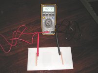
Test sample on HIPS, 2mm thick polystyrene sheet - three (3) years without appreciable change in the surface resistivity of about 350MOhm/sq. This sample has two light coats and has not been subject to flexing. I checked the resistance a couple of minutes ago (refer to the atached JPG).
I apply Licron at 25-30degC, 40%-50% humidity in shade (which is average for Perth). When apllied as a light coat it dries almost instantly.
Note - Licron is very difficult to remove without damaging membrane (I tried Methyl Alcohol, thinners, MEK, toluene and isopropyl without success).
Regards
Membrane - two (2) years and still going.
Test sample on HIPS, 2mm thick polystyrene sheet - three (3) years without appreciable change in the surface resistivity of about 350MOhm/sq. This sample has two light coats and has not been subject to flexing. I checked the resistance a couple of minutes ago (refer to the atached JPG).
I apply Licron at 25-30degC, 40%-50% humidity in shade (which is average for Perth). When apllied as a light coat it dries almost instantly.
Note - Licron is very difficult to remove without damaging membrane (I tried Methyl Alcohol, thinners, MEK, toluene and isopropyl without success).
Regards
Attachments
The Licron diaphragm is installed and working fine. I read 15-30 ns conductivity between a couple washers laid on the diaphragm a couple inches apart.
We'll see if it continues to work. It seems like one can of the Licron should be good to build a lot of drivers, maybe a couple hundred of the Quad sized drivers.
I_F
We'll see if it continues to work. It seems like one can of the Licron should be good to build a lot of drivers, maybe a couple hundred of the Quad sized drivers.
I_F
I_F
Glad that the speaker is working.
Based on your surface resistance measurement of 50Mohm/sq I guess the Licron coat(s) was(ere) heavy, which may have caused forming of the droplets.
If there is no perceivable (or better measurable) difference in the speaker sensitivity your are OK") .
.
My speakers have been working with Licron two years, I'll drop you an e-mail when the membrane coating fail
Regards
Glad that the speaker is working.
Based on your surface resistance measurement of 50Mohm/sq I guess the Licron coat(s) was(ere) heavy, which may have caused forming of the droplets.
If there is no perceivable (or better measurable) difference in the speaker sensitivity your are OK
.My speakers have been working with Licron two years, I'll drop you an e-mail when the membrane coating fail
Regards
Re: Coating both sides of the diaphragm
My recollection of what Strickland said is that it worked fine in Florida where the relativel humidity is high, but did not work when they moved to Arizona, where the humidity was low...
The Licron is the Tin-Oxide based anti-static stuff??
What about a spray'd Nylon? Anyone make that?
What sort of surface does the Licron provide when dried on the Mylar, and did you say it doesn't want to come off??
_-_-bear
Brian Beck said:This is the same argument, also overlooked at times, that teaches that you should not coat the stators with anything approaching a “perfect” insulator – the speaker won’t play! Strickland and Janszen both wrote about how using Teflon or polyethylene coating on stators (stator wires in particular) would rob the air gap of its electric field by simple voltage division between a small resistor and a larger one. They recommended PVC coating, since PVC is about 1000 time more conductive than PE.
My recollection of what Strickland said is that it worked fine in Florida where the relativel humidity is high, but did not work when they moved to Arizona, where the humidity was low...
The Licron is the Tin-Oxide based anti-static stuff??
What about a spray'd Nylon? Anyone make that?
What sort of surface does the Licron provide when dried on the Mylar, and did you say it doesn't want to come off??
_-_-bear
Can anyone explain to me why coating the stators with an insulator is supposed to kill the output from a driver? I have heard this said in a few different places and it just doesn't seem to match up with reality. The air between the stators and the diaphragm is an insulator, so how can adding another layer of insulation effect the performance of the driver? Adding additional insulation will increase the capacitance of the driver, and will reduce the maximum excursion of the diaphragm, but that's about all I can see happening.
Also, a measuring resistance is not the same thing as measuring sheet resistance. Sheet resistance is accurately measured by using a 4 point probe. A known current is passed between two of the points and the voltage is measured across the other two points. Then the whole thing is rotated 90 degrees and another set of measurements are made. The resistances (measured voltage/applied current) are plugged into the Van der Pauw equation which can then be solved for sheet resistance:
exp(-pi*Ra/Rs)+exp(-pi*Rb/Rs)=1
In the case where the resistivity is isotropic, the formula becomes
2*exp(pi*R/Rs)=1 -> Rs= -(pi*R)/ln 2
R, Ra, Rb are the calculated resistances, and Rs is the sheet resistance.
In practical terms, the coating won't be uniform, and not many people have a four point probe, or a calibrated high voltage low current source, so a resistance measurement is what we have to live with and it is adequate. Just don't call it sheet resistance!
I_F
Taking a complete guess at the answer to the question about coating the stators...
It doesn't kill the output. Obviously Martin Logans are coated and JanZen and Acoustat use PVC insulated wire, etc...
IF and only IF the insulation is *very good* - as it was in Stickland's case (Acoustat) using Teflon (r)(tm DuPont) insulated wires - then I am hypothesizing that the voltage gradient outside the insulation was *reduced* sufficiently in a dry air environment.
It seems that the idea is that a voltage gradient would be set up, wherein the air + insulation becomes a capacitive dielectric, getting charged. The "leaky" quality of the PVC insulation becomes a minor benefit as it permits sufficient charge (voltage & current) to leak so as to keep the air dielectric's field charged...
That's my seat-o'-da-pants hypothesis.
Anyone else?
_-_-bear
That's exactly right. Good explanation. Martin Logan's powder coating is probably loaded with carbon to make it sufficiently leaky so as to keep the air gap's electric field high. But the resistivity is still high enough to reduce the energy of any arcs and for safety’s sake.
Guess
Hi,
the problem with high resistance stator coatings is that in case of an overload the diaphragm touches the stator and will stay attached for a while and that after the membrane disconnects itself from the stator the output will be reduced for a while . Coatings with a lower surface resistance will recover more quickly.
For a music signal the resistance of the coating is of minor value. The problem of high insulative coatings like Teflon or PE is rather a very low dielectric constant. The higher this constant the less is the loss of signal over the coating thickness (capacitive voltage divider with the air). While Teflon is very low (2-3) PVC and Nylons are higher (4-12). So PVC and Nylon permit thicker insulations which is good in safety tems without giving up too much on efficiency.
yap
Calvin
- Status
- This old topic is closed. If you want to reopen this topic, contact a moderator using the "Report Post" button.
- Home
- Loudspeakers
- Planars & Exotics
- ESL diaphragm coating