I'm starting this thread because I don't want to hijack the other long running "DIY'ing ribbon" thread.
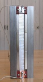
I've built a prototype ribbon tweeter using (relatively) simple and inexpensive materials. My end goal is to build ~36" multi segment ribbon tweeters for a line array. My prototype represents one of these segments and the powered portion of the ribbon is 5.25" long. It's open back so I can run it either as a dipole or absorb the rear wave without having a lot of problems with cavity resonances.
I don't have acces to a machine shop and I'm too cheap to pay for services so I ddid not want a design that required complicated machining of huge hinks of steel. I bought mine from Online Metals but McMaster Carr probably also has it. I've used standard 5/8" square 10018 steel bar bolted together with simple 1/4" machine screws.
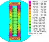
The ribbon is made of thin alumiinium foil available and cheap from McMaster Carr. I've used .25 x .5 x1.75" N40 Neodymium magnets. These cost a few bucks +- each. These are very powerful magnets and a little tricky to handle. I wanted to avoid designs that required huge, limb threatening blocks of Neodymium. Femm shows me getting ~ .5 tesla across a half inch gap - not Raven class but not bad. Doubling to 1 tesla would only buy me 6 db but would make the driver much more complicated and expensive. Since my eventual goal is to run 36" inches of these ribbon, I don't think volume will be a problem.
Still in the works is a matching transformer. I've odered a couple types of ferrite torroids and will try winding my own. Until then, I've played around with the driver putting a four ohm resister in series with the foil and driving it from a 100 w amplifier.
Total cost of this single driver is ~$35. How does it sound? I just finished it a few hours ago so I've got very little time on it. Running it full range, it sounds surprisingly good. I was able to stretch the ribbon by turning up the volume too high while playing it full range. I've also tried it with 20uf capacitor in series to role off the low end. This reduces excursion a lot.
I've built a prototype ribbon tweeter using (relatively) simple and inexpensive materials. My end goal is to build ~36" multi segment ribbon tweeters for a line array. My prototype represents one of these segments and the powered portion of the ribbon is 5.25" long. It's open back so I can run it either as a dipole or absorb the rear wave without having a lot of problems with cavity resonances.
I don't have acces to a machine shop and I'm too cheap to pay for services so I ddid not want a design that required complicated machining of huge hinks of steel. I bought mine from Online Metals but McMaster Carr probably also has it. I've used standard 5/8" square 10018 steel bar bolted together with simple 1/4" machine screws.
The ribbon is made of thin alumiinium foil available and cheap from McMaster Carr. I've used .25 x .5 x1.75" N40 Neodymium magnets. These cost a few bucks +- each. These are very powerful magnets and a little tricky to handle. I wanted to avoid designs that required huge, limb threatening blocks of Neodymium. Femm shows me getting ~ .5 tesla across a half inch gap - not Raven class but not bad. Doubling to 1 tesla would only buy me 6 db but would make the driver much more complicated and expensive. Since my eventual goal is to run 36" inches of these ribbon, I don't think volume will be a problem.
Still in the works is a matching transformer. I've odered a couple types of ferrite torroids and will try winding my own. Until then, I've played around with the driver putting a four ohm resister in series with the foil and driving it from a 100 w amplifier.
Total cost of this single driver is ~$35. How does it sound? I just finished it a few hours ago so I've got very little time on it. Running it full range, it sounds surprisingly good. I was able to stretch the ribbon by turning up the volume too high while playing it full range. I've also tried it with 20uf capacitor in series to role off the low end. This reduces excursion a lot.
Attachments
I got the magnets at :
http://www.engconcepts.net
Good prices and good service.
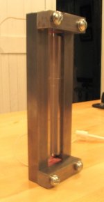
FYI: Here is one more picture, of the back.
http://www.engconcepts.net
Good prices and good service.
FYI: Here is one more picture, of the back.
Attachments
Hi dhenryp,
Have you considered adding a couple rear iron cross braces in an effort to make the magnetic field across the ribbon more uniform? The metal on top and bottom gives a non-uniform transverse magnetic field, which is not ideal. The rear cross braces can be of modest width, and could be covered with a thin layer of wool or fiberglass to absorb some of the rear reflections. Otherwise, you may want to use aluminum rear cross braces on the top and bottom to keep the transverse magnetic field more uniform over the entire ribbon, although this will come at the expense of lower efficiency.
You may also want to reduce some of the front diffraction created by the deep magnetic cavity and sharp front edges by adding an angled or rounded front baffle plate. Most ribbons do this. You will also probably measure a SPL bump due to the cavity resonance, but this should be near 20Khz, and probably not worth filtering, which is a nice benefit of a narrow 0.5" ribbon.
linesource - Thanks for the comments. I'm anxious for feedback since everything I know on the subject I've picked up in bits in pieces on the web or forums like this.
I know the flux density in the vertical pole pieces is much denser at the ends than in the center but it does not appear to affect the linearity of the field in the gap. I've run femm with the top and bottom cross pieces removed and it does not seem to improve gap linearity and, as you said, reduces field strength by ~ 40%. What is the benefit of distributing the field in the poles more evenly?
Regarding the diffraction effects - I had planned to put 3/4" quarter round, or maybe just straight 30 degree angle pieces, on the front and the back. In the back, I might add 1/4" felt over top of the quarter round so that its surface is even with the surface of the magnets. How does that sound? This is just a prototype so I may not fiddle with this stuff until I build the final tweets.
Thanks again,
Denis
The design is not an exact copy of anything else I've seen but ribbons are so simple I can't take too much credit for original work. The biggest contributor to the design is the femm magnetic simulation tool. I've played around with it a lot over the last several months trying to come up with a simple efficient magnetic circuit.
As I said at the top, I wanted something that had the potential for high performance but did not require a machine shop to produce. The "machine shop" I used to build this consisted of a sawsall, a bench grinder to clean up the sawsall cuts, a drill (I have a drill press but a hand drill wood work as well), and a tap to thread the holes in the vertical pole sections.
I crazy glued the magnets on. Without glue, they tend to repell each other and leave ~ 1/8" space between each of them. I may go to 5 minute epoxy. Crazy glue dries too quickly and these magnets are strong enough to have a mind of their own when you are trying to force them into position.
I've upped the capcitor to 40 uf to give me a first order filter (with the 4 ohm resistor) of 1k. This may turn out to be too low, but it's been OK so far. All I have set up in my basement right now is an old receiver, so I've only listened to FM radio so far. I've turned the (100w into 8 ohms) receiver all the way up and given my resistance assumption, I was probably applying less than 1 watt to the ribbon. It was too loud to listen to comfortably at a distance of ~ 3 feet - so this thing is at least moderately efficient. I've got lspcad/justmls but I'm not set up for measurements yet. I may take out my Radio Shack meter to get a rough idea. As I said at the top, it sounds pretty clean with no buzzes or obvious distortion (as long as I filter out the really low end - I did get some interesting noises when I stretched out the ribbon pleats by playing full power full range).
I made my own ribbon pleating "tool". Home Depot sells a flexible rubber "cord" that is used to keep screens in wooden screen doors/windows. It's ~ 3/16 inch diamter, hollow with, with 8-10 ridges running down the length. I stuck some finish nails in the center of two pieces cut to ~ 3/4 inch, stuck them in the crudest possible jig so they will roll against each other like gears. I get pretty good ribbons with this. It takes about 20 seconds to pleat a 6 inch ribbon. This may get refined as I go along, but maybe not.
I don't have a milliohm meter, but using what I have (.1 ohm lsb), it is definitely less than .1 ohm. I've read somewhere (the Raven site?) that a similar sized commercial ribbon is ~ .02 ohm so I'm guessing mine is probably in the range 0f .02 - .04. I should be able to get a better estimate by comparing the voltage drop across the four ohm resistor to the drop across the ribbon for a given frequency, say 3k. I have to dig out my signal generator and hook it up. Even six of these ribbons would probably only get me something on the order of .1 - .2 ohms - still too low for direct drive.
The next step is the Xformer. I should receive my ferrite torroid cores tomorrow. I'm going to start with an 8-10 turns ratio (assuming I can fit all the wire on the relativey small cores I bought). I've read that the resulting impedance would be = turns ratio **2 * ribbon impedance. This should get me into the single unit ohms range, the exact value depends on the ribbon resistance.
Stay tuned.
Denis
Transformer Version 1
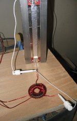
I got my two types of ferrite toroids today CWS Coil Winding Specialist and tried winding some transformers. One is item F-150-W: $5.00 each (I think the code is Ferrite - 1.50 inches OD - Type W composition) and the other is F-114-H : $2.65 each (Ferrite - 1.14 " OD - Type H). Both have a .75 inch "hole". I first tried winding them both with 37 turns on the primamry and 4 (or maybe 5) on the secondary. I put 20 uf capacitor in series. The primary is a dead short at low frequencies so you need some sort of high pass filter. All I have on hand now is 16 gauge magnet wire so 37 turns the maximum I can put on one layer. I've got some smaller wire coming so I'll do some more experimenting then.
Both of these worked, but no well. I could drive both directly from my amp (i.e. no series resistor) and they sounded OK at low to moderate levels. Above this, it distorted badly. After trying various secondary winding turns I hit upon: 37 turns primary - 10 secondary using the F-150-W. This works really quite well. I can play it very loud with no really obvious distortion. This is not a very scientific analysis but it's the best I can do for the moment. Turning the amp almost to the max, the driver was too loud to comfortably listen to at three feet. I set up my Radio Shack Sound level meter about three feet from the ribbon. The Meter showed peaks of ~ 105db. I had it set at A weighting, fast response time.
I need to find a good book or website to help me understand better how to determine both the turns ratio and the number of turns. Below is the picture of my Version 1 transformer hooked up to the ribbon tweeter.
Denis
Attachments
Aren't audio transformers usually made from steel laminations or even permalloy/amorphous cores? I know you only need ~1kHz and up, but ferrite has extremely low permeability....W composition is u=6, permalloy is around 20,000 I think. Primary inductance must be very low as a result.
http://hyperphysics.phy-astr.gsu.edu/hbase/magnetic/indtor.html
I also think the turns ratio can't be optimized for a normal amp. Your ratio is 3.7:1 yielding an impedance transformation of 13.69:1; I wouldn't think the dynamic impedance of the system was above 1 ohm + the capacitive reactance.
If it works, it works though. I'm just armchair quarterbacking.") You must have a forgiving amp.
You must have a forgiving amp.
You might consider looking into those small PC mount Talema toroids that Digikey sells. I think they are only about $9-11. I have used them for audio and >1 kHz the distortion is -100dB down. The 1:2 voltage ratio model I used was flat 20Hz-20kHz small signal. I believe they have ratios up to 48:1 if you do series primary and use a single (or parallel) secondaries.
Another idea for cores would be to get the Edcor line transformers and remake them.
http://hyperphysics.phy-astr.gsu.edu/hbase/magnetic/indtor.html
I also think the turns ratio can't be optimized for a normal amp. Your ratio is 3.7:1 yielding an impedance transformation of 13.69:1; I wouldn't think the dynamic impedance of the system was above 1 ohm + the capacitive reactance.
If it works, it works though. I'm just armchair quarterbacking.
You must have a forgiving amp.You might consider looking into those small PC mount Talema toroids that Digikey sells. I think they are only about $9-11. I have used them for audio and >1 kHz the distortion is -100dB down. The 1:2 voltage ratio model I used was flat 20Hz-20kHz small signal. I believe they have ratios up to 48:1 if you do series primary and use a single (or parallel) secondaries.
Another idea for cores would be to get the Edcor line transformers and remake them.
Repost of Talema data from my samples. I can send you a 35VA unit if you want to experiment. Maybe the leakage inductance is too high though. The smaller cores are way better on this measurement.
1.6VA as line input
==============
2:1
Primary inductance: 4.5H
Primary interwinding capacitance: 200pF
with 13k secondary load
-0.5dB at 20Hz
-0.3dB at 20kHz
The bad news is that distortion is on the order of 0.6% at 20Hz, -0.05% at 250Hz, 0.001% at 500Hz, and unmeasurable at higher frequencies. This would be excellant as line input for a tweeter amp, but the primary inductance just doesn't appear to be high enough for the low frequencies.
35VA as OPT
=========
27:1
Primary inductance: 146H
Primary leakage inductance: 10.5mH
Primary interwinding capacitance: 1.4nF
I have built amps that can direct drive 0.1 ohm Apogee ribbons and was not happy with the sound. I then converted to a 5.8 micron ribbon that increase the restance to 0.35 ohms, tripled efficiency, and it sounded wonderful with the direct drive amp. Much better than with a transformer.
Sputtering very thin aluminum on a 2 micron thick film will create a more physically robust ribbon than pure aluminum, but also a low efficiency ribbon relative to its weight since the electrical resistance will be much higher than 100% AL. Most ribbons are also corrugated(pleated) to increase horizontal stiffness. A thin film ribbon may not hold this corrugation, and the ribbon is likely to "fold" from the magnetic field gradients.
Most commercial tweeters seem to use 8-10 micron aluminum, as this holds a corrugation well and is a good compromise between weight and physical robustness. 5.4 micron thick pure aluminum foil is thinnest I use on long, wide bandwidth ribbons.
Here is some resistance data for pure aluminum for 0.5 x 36" ribbon, where I assumed 42" of aluminum to account for the corrugations and connection ends.
microns ohms for 0.5"x42" AL
2..............1.0600
3............. 0.7067
4............. 0.5300
5............. 0.4240
6............. 0.3533
7............. 0.3029
8............. 0.2650
9............. 0.2356
10........... 0.2120
11........... 0.1927
12........... 0.1767
13........... 0.1631
14........... 0.1514
15........... 0.1413
16........... 0.1325
17........... 0.1247
18........... 0.1178
19........... 0.1116
20........... 0.1060
21........... 0.1010
22........... 0.0964
23........... 0.0922
24........... 0.0883
25........... 0.0848
transformer design
Nice ribbons there!
I think the distortion may be the ferrite saturating or the transformer not presenting enough inductance. You need to consider 2 things:
1) A minimum number of turns to avoid saturation:
The equation is V = BANw
where
V is the peak primary voltage in volts
B is the flux in Tesla (probably want no more than about 0.5T for ferrite - check core spec)
A is the cross-sectional area of the core in *square metres*
N = number turns
30 turns is prob about the minimum for a 2cm^2 core area
2) The primary inductance - this will be equal to N^2 * the specific inductance of the core, usually spec'd in nH/sqrt(turns)
The transformer presents a load to the amp equal to the reflected load [ (ratio^2) * ribbon resistance] in parallel with the primary inductance.
For an 8 ohm load (say), you probably want the inductive component to be 5 or 10x greater at the lowest frequency of interest so that it is insignificant compared to the real load.
So if you are crossing over at 1kHz, you probably want an inductance of 6-12mH.
All very rushed and from memory so please double check!
Other things to consider are very low DCR secondaries and connections to the ribbons.
Cheers
tiroth said:Aren't audio transformers usually made from steel laminations or even permalloy/amorphous cores? I know you only need ~1kHz and up, but ferrite has extremely low permeability....W composition is u=6, permalloy is around 20,000 I think. Primary inductance must be very low as a result.
http://hyperphysics.phy-astr.gsu.edu/hbase/magnetic/indtor.html
I also think the turns ratio can't be optimized for a normal amp. Your ratio is 3.7:1 yielding an impedance transformation of 13.69:1; I wouldn't think the dynamic impedance of the system was above 1 ohm + the capacitive reactance.
If it works, it works though. I'm just armchair quarterbacking.
You might consider looking into those small PC mount Talema toroids that Digikey sells. I think they are only about $9-11. I have used them for audio and >1 kHz the distortion is -100dB down. The 1:2 voltage ratio model I used was flat 20Hz-20kHz small signal. I believe they have ratios up to 48:1 if you do series primary and use a single (or parallel) secondaries.
Another idea for cores would be to get the Edcor line transformers and remake them.
The "W" material has a permeability of 10000 and the "H" material has a permeability of 15000. I agree that the 3.7 turns ration is way too low but it's the best I could come up with last night with the wire I had. Here are the specs:
http://www.cwsbytemark.com/cws_catalog/section2/2_04_magproperty2.pdf
The F-150-W as an AL of 8800 mh per thousand turns so my input inductance should be 8800 * 37/1000 = 325 mh, if I understand the specs correctly.
I'll take a look at the transformers you mentioned. Maybe they are what I need and would not take any extra work.
Thanks,
Denis
Stocker said:perhaps this is just a ribbon-noob question, but why not direct drive this low impedance from a low voltage, high current amp?
With a ribbon of .02 ohms, you would end up losing most of your power in what is usually insigificant resistances like speaker wire, interconnects etc.
Linesource - I'm using .0005 inch aluminium which (I think) works out to 12.7 micron. Based on your very handy chart, my resistance for a 7" strip (an 1.7 inch to account for corrugations etc.) should give me ribbon resistance of ~ .028 ohms - pretty close to my assumption.
Thanks for the info.
Denis
Thanks for the info.
Denis
- Status
- This old topic is closed. If you want to reopen this topic, contact a moderator using the "Report Post" button.
- Home
- Loudspeakers
- Planars & Exotics
- Another DIY Ribbon thread