The magnet force direction (N to S) is actually the main force and direction.
Otherwise the speaker would not work.
You are however right in the sense that magnets will repel just by sitting side by side but that is just a small force compared to the force between N and S pole.
If You had been more precise in the force arrows, then they would be facing diagonally as they are very much affected by the other pole bar.
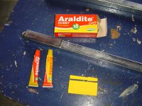
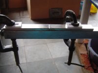
Even with glue, ultil it was dry, i needed to place a holder when i was assembling my tweeter. So i can affirm that you need alot of strength to place they touching each other on the steel bar. It's hard but not impossible! 
Now, i took off all magnets from the steel bar, broke off some magnets (i have some spares) and now i'm making a new enclosure
PS: Femmview is from Dahlberg site.
Now, i took off all magnets from the steel bar, broke off some magnets (i have some spares) and now i'm making a new enclosure
PS: Femmview is from Dahlberg site.
Attachments
Last edited:
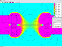
The FEMM-picture is from Dahlbergs own design with 2 rows of magnets side by side with a few mm spacing between each row.
This is to get a more even/straight flux field for the ribbon that You don't get with single row.
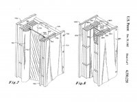
I attached one image of the midrange ribbon structure used in the 1984 Apogee Fullrange Speaker. As you can see Apogee also used two rows of magnets with a small gap between, and describes in the patent how this provides both an improved uniformity magnet field and also an improved self centering capabilty. This 2" wide, 84" long midrange ribbon is crossed with 1st order slopes at 360hz and 10kHz. Bass is provided by a large planar woofer panel with a single sided magnet motor. Treble is provided by a 0.5" wide x 84" long "dual sided" ribbon ... a front and rear ribbon separated by 0.5" in the same field gap. The longer tweeter ribbon provides enough ohms of resistance to not require a step-up transformer.
Personally, I have gotten the best results using a single wider magnet.
Attachments
Hello Sonegatti, nice work indeed! What dimensions have your magnets and where do you get them from? Regards Michael
Thanks Michael, i'm using magnets with 100x20x6mm N50 ordered in China Rare Earth Permanent Magnet Company, Neodymium Magnets Manufacturer, Permanent Magnets Supplier, was a special order, thats why i ordered 100 pieces.
The longer tweeter ribbon provides enough ohms of resistance to not require a step-up transformer.
Personally, I have gotten the best results using a single wider magnet.
For an easier construction, i chose a wider magnet too, but i'm with some problems to find 5 microns aluminium foil, even in industries i can't find that! I got around 0,1R with a 18mm wide and 1,65m long in a 12 microns aluminium foil.
^^^^ Same here , ended up using magnets that where 100x25x25 MM single row, does the double row bring anything to the table ....what about gaps between mags vertically , anything there .?
WOW, neodymium? Can you see the little black-holes on the gap?
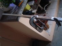
I'm not an artist when drawing, but i drew this layout for my ribbon tweeter shield (and magnetic field "amplifier"
), i did the thickest i can (hydraulic bender is limited 90° edge in #1/8 plate).Attachments
Using ferrite magnets system consist of 240 magnets no way in neo...cheap
Costs about 9USD each (with shipping and 10% of taxes), two years ago.
Tell me the new prices if you make an order!
Thanks!!
Sorry for the ignorance but what exactly is the difference between the ribbon speakers and plannar?
Seems like I have seen ribbon tweeters and ribbon midrange on the Maggies so I start to get confused. Do the Plannar and Ribbons sound similar?
Seems like a smaller plannar can cover a wider bandwidth, no?
Seems like I have seen ribbon tweeters and ribbon midrange on the Maggies so I start to get confused. Do the Plannar and Ribbons sound similar?
Seems like a smaller plannar can cover a wider bandwidth, no?
Well a planar speaker is mostly called that way because it has a flat transducer.
It has nothing to do with if it has a ribbon tweeter or not.
Most of the time magnetostatic speakers are referred to as planars and electrostatic speakers are not. Even though they are flat.
It has nothing to do with if it has a ribbon tweeter or not.
Most of the time magnetostatic speakers are referred to as planars and electrostatic speakers are not. Even though they are flat.
Ribbon Pleating Tool
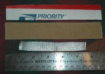
Here is a pleating tool that is totally FREE! get a USPS Priority mail box like the 12 1/16 X 2 11/16 X 13 7/16 size. Cut off pieces carefully of the size needed for ribbon length. Wet them until the brown side comes off easily. After drying, ready to use. These make about 7 total pleats per inch, 14 angles.
Here is a pleating tool that is totally FREE! get a USPS Priority mail box like the 12 1/16 X 2 11/16 X 13 7/16 size. Cut off pieces carefully of the size needed for ribbon length. Wet them until the brown side comes off easily. After drying, ready to use. These make about 7 total pleats per inch, 14 angles.
Attachments
Thanks for that post Brunob; I've had my suspicions about FEMM. Some old school knowledge about magnet shapes had me puzzled as to why neodymium bar magnets are used so religiously in these ribbon designs. The field strength through the length of a cylinder is much better than through the side of neodymium bar magnets. In many designs the choice is an obvious easy way to build it. But others are just a very inefficient approach.(no build advantage to the bar magnets)I measured the magnetic fields using a Hirst gaussmeter of long and short magnets systems. I did NOT observe a strong decrease the magnetic field in the ribbon gap for a long versus a short system. Seems that FEMM is wrong here.
Bruno
Then I made the discovery that FEMM was not showing this much at all (if at all) I realize magnetic field design can be elusive. but generally, a good old fashioned weight lifting test gives you a good idea of what you have got. And on that basis I more than doubled my field strength with cylinders. This is both a cost savings or in the case of those wishing to build an open back (dipole type) ribbon, the efficiency without the back iron. I think some Gaussmeter testing here would give me some relief.
Thanks for that post Brunob; I've had my suspicions about FEMM. Some old school knowledge about magnet shapes had me puzzled as to why neodymium bar magnets are used so religiously in these ribbon designs. The field strength through the length of a cylinder is much better than through the side of neodymium bar magnets. In many designs the choice is an obvious easy way to build it. But others are just a very inefficient approach.(no build advantage to the bar magnets)
Then I made the discovery that FEMM was not showing this much at all (if at all) I realize magnetic field design can be elusive. but generally, a good old fashioned weight lifting test gives you a good idea of what you have got. And on that basis I more than doubled my field strength with cylinders. This is both a cost savings or in the case of those wishing to build an open back (dipole type) ribbon, the efficiency without the back iron. I think some Gaussmeter testing here would give me some relief.
Any pictures ?
Peter
Hi all ribbon enthusiasts! I'm tempted to build some wide range ribbons myself, they look so fffing simple to build. But some quidance is needed, all opinions are much appreciated.
The magnets:
- Which one of these dimension is better in your opinion in "normal" structure? Does the 0,5" x 0,5" give more concentrated magnetic field than the other for example?
a) 4" x 1" x 0,25": cPath_1_5 | products_id_1056 | N45 Neodymium Magnets 4 in x 1/2 in x 1/2 in Rare Earth Block - Applied Magnets & WindMax Wind Turbines
b) 4" x 0,5" x 0,5": cPath_1_5 | products_id_1056 | N45 Neodymium Magnets 4 in x 1/2 in x 1/2 in Rare Earth Block - Applied Magnets & WindMax Wind Turbines
- Which above dimension would be better if the magnetic structure would be made with two side-by-side magnets (like this http://www.diyaudio.com/forums/planars-exotics/50162-another-diy-ribbon-thread-75.html#post2664886).
- In you opinion, is it worth doubling the budget to make the side by side magnets? Does it reduce even order harmonics ~10dB, give 3-6dB more sensitivity etc.?
The ribbon:
- I like the looks of smooth ribbons over corrugated ones. Does the ribbon resonate too much if it's not corrugated? I would maybe just roll it with dough roller to get some tiny-tiny patterns going, at least try it. How Fountek controls the resonances for example? I think they use smooth ribbons.
- 12µm aluminized mylar as ribbon material, yes or no? Smoothier FR maybe compared to uncorrugated alu foil, but somewhat reduced efficiency?
The size of the ribbon:
- I would like to be able to play down to ~200-300Hz with some crank-it-up capacity and good linearity, and propably XO 6dB/oct. If the ribbons are 2m tall, how wide the ribbon should be approx? Will 0,5-1" wide ribbon manage it also in dipole configuration, if the baffle width is set appropriately?
General:
- How hard it is to make a very good sounding wide range ribbon, comparable to Magnepan ribbons for example?
- Best source for the magnets?
. But some quidance is needed, all opinions are much appreciated.The magnets:
- Which one of these dimension is better in your opinion in "normal" structure? Does the 0,5" x 0,5" give more concentrated magnetic field than the other for example?
a) 4" x 1" x 0,25": cPath_1_5 | products_id_1056 | N45 Neodymium Magnets 4 in x 1/2 in x 1/2 in Rare Earth Block - Applied Magnets & WindMax Wind Turbines
b) 4" x 0,5" x 0,5": cPath_1_5 | products_id_1056 | N45 Neodymium Magnets 4 in x 1/2 in x 1/2 in Rare Earth Block - Applied Magnets & WindMax Wind Turbines
- Which above dimension would be better if the magnetic structure would be made with two side-by-side magnets (like this http://www.diyaudio.com/forums/planars-exotics/50162-another-diy-ribbon-thread-75.html#post2664886).
- In you opinion, is it worth doubling the budget to make the side by side magnets? Does it reduce even order harmonics ~10dB, give 3-6dB more sensitivity etc.?
The ribbon:
- I like the looks of smooth ribbons over corrugated ones. Does the ribbon resonate too much if it's not corrugated? I would maybe just roll it with dough roller to get some tiny-tiny patterns going, at least try it. How Fountek controls the resonances for example? I think they use smooth ribbons.
- 12µm aluminized mylar as ribbon material, yes or no? Smoothier FR maybe compared to uncorrugated alu foil, but somewhat reduced efficiency?
The size of the ribbon:
- I would like to be able to play down to ~200-300Hz with some crank-it-up capacity and good linearity, and propably XO 6dB/oct. If the ribbons are 2m tall, how wide the ribbon should be approx? Will 0,5-1" wide ribbon manage it also in dipole configuration, if the baffle width is set appropriately?
General:
- How hard it is to make a very good sounding wide range ribbon, comparable to Magnepan ribbons for example?
- Best source for the magnets?
Last edited:
I think the field strength would be stronger the closer the 2 poles are. And use N52 magnets. More expensive, but the strongest available so far. 1/2 inch across should be about right? They are stronger the bigger they are. Steel "U" shaped frame probably doesn't help the field, but sure makes it easier to keep the magnets in place.
http://www.diyaudio.com/forums/planars-exotics/212165-diy-4-inch-ribbon-tweeter.html
I don't know much about difference of ribbons. I have seen ones that are pattern dented but most were corrugated. metallized mylar I hear is no good. Too much resistance and easily ruined by power.
I buy the magnets from K & J Magnetics, Inc.
I have progressed a little and got some quotes for 4" x 1" x 1" neomagnets. N42 grade, no need for stronger (around 200lbs pull force) and the price increases fast with higher grades. Do you think they are too monster sized magnets, pure agony to handle?
I have also simulated the "traditional" and the "double magnet" construction with FEMM and noted their difference. I think traditional magnet system is forgiving if one wants to change the air gap width, and actually the x and z axis "Bl-curve" across the gap to both directions is good if the magnet width is sufficient for the air gap's width.
Double magnet system (the gap between the magnets) needs to be fine tuned for air gap width and does not react too well if it's changed. It seems that with the gap between the magnets it's better to err with too small than too large gap. When tuned right, I think double magnet surpasses the traditional construction. But it would cost humongously to build ~2m tall ribbons with monster magnets, and the construction would weight at least "decetly". With traditional design one gets away with half the cost and half the weight.
Traditional magnet design drives the sides/edges (x axis) of the ribbon somewhat harder than the center, on the other hand the double magnet system drives the sides/edges with somewhat less force than the center. Traditional transitions the force smoothly, double magnet system stays constant long way but then the force transition is more abrupt very close to the magnets. I wonder how this translates to distortion figures.
Regarding "xmax", traditional design gives smoothly falling Bl, that usually means even order distortion (sharp fall in the Bl rises higher/odd order harmonics). With traditional design, and with above mentioned 1" wide magnet and 1" air gap, the "xmax" is still around +/- 7mm (according to FEMM, points where the Bl has dropped around -15%).
I think I will start off with the traditional design. If I go mad in the future, I can always buy more magnets.
Last edited:
.... 4" x 1" x 1" neomagnets. N42 grade....
pure agony to handle?
I doubt you will be able to pull two magnets apart
and I expect two magnet just half a meter apart will come flying and clash like hell
so... how to handle them ?
do I need to say more
- Status
- This old topic is closed. If you want to reopen this topic, contact a moderator using the "Report Post" button.
- Home
- Loudspeakers
- Planars & Exotics
- Another DIY Ribbon thread