"balanced allpass" is the key word if your searching:
http://www.google.nl/search?hl=nl&q=All+Pass+filter+balanced&btnG=Zoeken&lr=
this one is very intresting:
http://www.filter-solutions.com/passive.html#allpass
en this is the schematic of an esl 63:
http://www.euronet.nl/users/temagm/audio/esl63/quad63_schematic_new.jpg
( http://www.euronet.nl/users/temagm/audio/index.htm )
Delay
Hi,
the delay line in the ESL63 is a balanced LC-Filter chain with a delay of 20µs per segment. I haven´t found out yet for which frequency!?
Additional to this delay function, the LC-chain works as a Lowpass-filter, so that just the small center-segment works under fullrange conditions. The farther out the segment the stronger the LP. This should assist in keeping the radiation pattern broad.
Anyway, I am not convinced that the whole thing works as it is supposed to do!
The radiation pattern is in praxis very narrow, which suggests that the diaphragm exhibits a lot of interference and standing waves. This is obvious because each ring segment of the membrane should be supported a spacer -which it is not!- to decouple each segment mechanically from its neighbour. A pulse coupled to the center of the diaphragm moves as a wave through the membrane toward the outer rim -where parts of it are reflected back. The same time discrete segments are coupled electrically through the delay line. Now how great is the possibility of the mechanical wave and the electrical delay to be not in phase with each other??
Sounds rather like a bendingwave transducer -think of a Manger- and a delay line mixed up alltogether! One solution could be to decouple each segment mechanically. But doing so this will probably reduce the efficiency -which isn´t high in the ESL63 anyway- even more.
To me there remains another question unanswered.
"Whats the point in generating a globe (point source) as radiation pattern?? In most living rooms a cylindrical pattern is far superior because of lesser interaction with the rooms walls.
There are two simple solutions to this problem.
a) building a line source with a curved transducer like MartinLogan, or
b) a planar line-source which is frequency corrected by RC-chains like Audiostatic does.
Both solutions are much simpler to build and reach comparable (imo even better) results.
@hilbren
Obviously You plan to build a ESL like Mr. Fikier described. So You know how to design the RC-chain for the frequency-correction (which too broadens the radiation pattern)
yap
Calvin
DIY
Hi hilbren,
well ask me!
Just finished a set of panels 25x125cm, 1mm D/S. Works with app. 1kV polarizing voltage and a 1:75 Amplimo or 1:100 Sombetzki transformer. The diaphragm is very taut and resonates at 180Hz. The frequency response is very linear (what a difference to ML-Panels ) and it can be coupled by a series Cap followed by a notchfilter (180Hz) from 200Hz on, giving app. 90dB/2,83V/1m. I haven´t heard it at maximum level yet, because my ears always gave up earlier. Dynamics are outstanding. You rather think of listening to a Horn but with a lot better low level resolution and neutrality!! Holy Cow 
It´ll probably be coupled to a dipol-bass-tower
Yeah
Calvin
Hi hilbren,
well ask me!
Just finished a set of panels 25x125cm, 1mm D/S. Works with app. 1kV polarizing voltage and a 1:75 Amplimo or 1:100 Sombetzki transformer. The diaphragm is very taut and resonates at 180Hz. The frequency response is very linear (what a difference to ML-Panels
) and it can be coupled by a series Cap followed by a notchfilter (180Hz) from 200Hz on, giving app. 90dB/2,83V/1m. I haven´t heard it at maximum level yet, because my ears always gave up earlier. Dynamics are outstanding. You rather think of listening to a Horn but with a lot better low level resolution and neutrality!! Holy Cow It´ll probably be coupled to a dipol-bass-tower
Yeah
Calvin
Panels
Hi hilbren,
Well, of course You´d like to know everything But I might just be planning to offer tose panels as a DIY Set.
But certain details can be revealed.
The stators are made from 1mm perforated sheet metal with very high open area but rather small holes. The stators are bended to cover app 30°. Size is 25X125cm, probably a big panel with 50x170cm will follow soon. The insulation is made up of 3 layers and different materials (among wich is a powdercoating process with a very special powder, no ordinary cheap epoxy or PU)
The D/S is 1mm because the panels are concepted for a working range fom app. 200Hz on. The diaphragm is 3.5µm strong and the coating is made from a special highly transparent solution I developed (Too I discovered a procedure, wherin the molecular structure of the material is altered to give the right resisitivity without beeing affected by humidity or aging. Hope to get that material soon. Should be the best diaphragm material what so ever). With these small spacings You get a voltage gradient of 1kV/mm with just 1kV. Most ESLs don´t go higher because latest at 1.5kV first hissing sounds occur. I managed to get 2kV from one panel without any noise at all. So my insulation is really good.
The capacity is 1.3nF and I get around 90db efficiency (2.83V/1m, rising to 93dB at 2m, because of the nearfield effect of the cylindrical wave).
The panels are braced by a custom made bowed aluminium profile of app. 10cm width (the crossection looks like a banana
 ). The panels themselves are finished very pretty in shiny black and are nicely transparent. The braces are silver anodized.
Calvin
Hi hilbren,
Well, of course You´d like to know everything
But I might just be planning to offer tose panels as a DIY Set.But certain details can be revealed.
The stators are made from 1mm perforated sheet metal with very high open area but rather small holes. The stators are bended to cover app 30°. Size is 25X125cm, probably a big panel with 50x170cm will follow soon. The insulation is made up of 3 layers and different materials (among wich is a powdercoating process with a very special powder, no ordinary cheap epoxy or PU)
The D/S is 1mm because the panels are concepted for a working range fom app. 200Hz on. The diaphragm is 3.5µm strong and the coating is made from a special highly transparent solution I developed (Too I discovered a procedure, wherin the molecular structure of the material is altered to give the right resisitivity without beeing affected by humidity or aging. Hope to get that material soon. Should be the best diaphragm material what so ever). With these small spacings You get a voltage gradient of 1kV/mm with just 1kV. Most ESLs don´t go higher because latest at 1.5kV first hissing sounds occur. I managed to get 2kV from one panel without any noise at all. So my insulation is really good.
The capacity is 1.3nF and I get around 90db efficiency (2.83V/1m, rising to 93dB at 2m, because of the nearfield effect of the cylindrical wave).
The panels are braced by a custom made bowed aluminium profile of app. 10cm width (the crossection looks like a banana
). The panels themselves are finished very pretty in shiny black and are nicely transparent. The braces are silver anodized.Calvin
Bringing an old thread up again.. I've been thinking about the way the ESL63 works (hence I found this old thread) and I came to a similar conclusion as Calvin above, that with no separators for the concentric rings there is a chance the naturally outward propagating wave from the centre ring will not be in perfect phase with the delayed signal going to the stator rings. Given that the all-pass filter actually rolls-off the high frequencies there will definitely be destructive interference at higher frequencies because the delay to the each stator doesn't have a linear delay.
It would be lovely to drive each ring from a digital delay line, but they would each need their own TX.
I would still be interested to know the actual inductor values in the delay line as I just guestimated them. I gather they are potted in wax, so perhaps this is why nobody has been able to measure?
Last edited:
I would still be interested to know the actual inductor values in the delay line as I just guestimated them. I gather they are potted in wax, so perhaps this is why nobody has been able to measure?
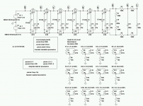
I have not had the opportunity to measure the inductors, but I can pass along some information on the topic.
The first attachment shows the simplified ESL63 model that Baxandall provided in his chapter on ESLs.
It uses the unbalanced form of the delay network rather than the lattice form.
There is a fair amount of coupling between the inductors since they are stacked side by side.
The second attachment shows a SPICE model that Mark Rehorst(diyAudio member I_Forgot) had been working on.
Plotted results and SPICE netlist are currently still available here:
Quad ESL-63
...with no separators for the concentric rings there is a chance the naturally outward propagating wave from the centre ring will not be in perfect phase with the delayed signal going to the stator rings. Given that the all-pass filter actually rolls-off the high frequencies there will definitely be destructive interference at higher frequencies because the delay to the each stator doesn't have a linear delay.
Tim Mellow published a JAS article on using an ESL with ringed structure like ESL63 but where sound velocity on diaphragm surface is considered.
Scitation: A dipole loudspeaker with a balanced directivity pattern
It is currently available for free download from his website here:
http://mellowacoustics.com/articles/Dipole_speaker_with_balanced_directivity.pdf
Other papers of interest here:
mellowacoustics.com | articles_and_papers
There is also a US patent application for the technique (US20120033834):
Patent US20120033834 - Apparatus With Directivity Pattern - Google Patents
Attachments
Thanks for the detailed info!
A friend managed to find the Baxandall / Borwick book with ESL63 explanation HERE
I haven't had time to read it but I will. Perhaps I need not ask this question if I had - but in that first image of the non-balanced all-pass filter are the capacitors actually the ESL stators, or are they physical capacitor components?
18H is massive! I had no idea the inductors were that big... my god!
Hi
re ESL -63 inductances: I think you will find that to compensate for the inductor winding capacitance and coupling between inductances, Walker has added a criss-cross network of 22 pF capacitors across each segment (see Mark Rehorst diagram in previous post) , which, in addition to the 22 pF anular capacitance of the stators, means the actual capacitance per section is 3 x the 22 pF drawn in the equivalent circuit. This in turn means only 6 H of inductance per stator segment is required, and this is formed by two 3 H inductors, one in series with each of segment of the two stators. So the actual inductors are 3 H (still big for air cored devices). This means too, that only 1/3 of the stator current is responsible for the acoustic radiation.
re propagating mechanical wave in the diaphragm: At mid and high audio frequencies, practically the only forces acting on the diaphragm are the electrostatic motor of the ESL (driving force which we want) and the purely resitive reaction (load) of the radiation impedance. So there is no unwanted mechanical wave in the diaphragm.
At low frequencies where the air is able to slosh around the ESL panel and avoid being compressed by the diaphragm, the moving air mass has the effect of adding mass to the diaphragm - and then you get the various resonances where the whole diaphragm moves at once. The mesh damping cloth in the ESL63 kills off these pretty quickly.
regards
Rod
Huh, usually books that are still under copyright are not available for download.A friend managed to find the Baxandall / Borwick book with ESL63 explanation
Yes, the capacitors in the simplified non-balanced schematic represent the ESL stator rings....in that first image of the non-balanced all-pass filter are the capacitors actually the ESL stators, or are they physical capacitor components?
Give the Baxandall text a read, and you will better understand how the lattice circuit relates to the simplified model. He also goes into detail on the purpose of the cross capacitor networks and the shorted turns.
If I recall correctly, Baxandall states the value of the lattice inductors are 3H although the effective value is larger due to the mutual inductance with the other inductors. Still massive though, and they have to be able to handle several kVrms too.18H is massive! I had no idea the inductors were that big... my god!
re propagating mechanical wave in the diaphragm: At mid and high audio frequencies, practically the only forces acting on the diaphragm are the electrostatic motor of the ESL (driving force which we want) and the purely resistive reaction (load) of the radiation impedance. So there is no unwanted mechanical wave in the diaphragm.
Since the diaphragm is under tension, applying a transient force at a discrete location could be likened to plucking a guitar string. The resistive air load should provide substantial damping to the diaphragm in comparison to a string. But next time you are measuring a segmented ESL, you might try driving only a single segment and ground all the others. You will find high-Q peaks and dips in the midrange that aren't there when the whole panel is driven uniformly or with resistance ladder network. The frequencies of the dips and peaks are dependent on the location of the driven segment. If response/phase is measured for each of the segments independently and than summed all the peaks and dips of the individual segment responses cancel each other out leaving the smooth expected response. My assumption is that these are higher order diaphragm modes that aren't easily excited when the diaphragm is uniformly driven. Thoughts?
On a related topic, you may have noticed Baxandall mentions that a reflections occurs at the outer edge of the ESL63 because the plane being used to emulate the point source is truncated. The reflection is not in the electrical delay line, which is properly terminated. The Mellow approach does not have this issue since it is emulating an oscillating sphere using a diaphragm the same size as the sphere. This requires a delay that varies for each ring, so would not be possible using a passive delay line technique like the ESL63.
- Status
- This old topic is closed. If you want to reopen this topic, contact a moderator using the "Report Post" button.
- Home
- Loudspeakers
- Planars & Exotics
- Esl 63 what type of coil for the delay line?