I think I read somewhere of a test, that as you approach the hv limit the diaphragm moves from the center to one of the two stators, is it true? But I did not understand precisely how the test should be done, with a sinusoidal signal on the stators? Someone can help me?
There are two limitations with respect to bias voltage:
1) Stability of the diaphragm. This is the one you described in your question. Basically when you apply charge to the diaphragm with the bias voltage the diaphragm will be attracted to both front and rear stators. In the ideal situation of perfect symmetry, the attractive forces would be equal and the diaphragm would stay centered. But if your construction isn’t perfectly symmetric, or random air pressure pushes the diaphragm off center, the diaphragm will be attracted more strongly to the closer stator. The diaphragm tension resists this attraction up to a point, but eventually the diaphragm may collapse to the stator. You can see/hear this happen without an audio signal playing. Lower the voltage, and you will see/hear the diaphragm pull free.
2) Ionization of the air in the gap between diaphragm and stator also puts a limit on the magnitude of the bias voltage you can use. Testing for this ionization can also be done with no audio signal playing. Increase the bias voltage until you start hearing a continuous hissing or crackling noise, and then back off until it stops. You can also use a neon lamp charge indicator to determine when ionization takes place by looking for increased flash rate from conduction thru the ionized air in the gap. Details on the neon lamp charge indicator here: http://www.diyaudio.com/forums/planars-and-exotics/153773-esl-technical-questions.html#post1958015, pic here:http://www.diyaudio.com/forums/plan...ogan-sequel-ii-dead-panels-7.html#post3731257
Soooo….which is the more restrictive limit? If you have a large diaphragm area with no dividing spacers, 1) will likely be more limiting. If you follow the general guideline to keep the largest unsupported diaphragm width no bigger than 100x the diaphragm-to-stator distance and properly tension the diaphragm then 2) will likely be more limiting.
You can see/hear this happen without an audio signal playing
"without an audio signal" means with the stators connected to the transformer or with the stators totally disconnected?
"without an audio signal" means with the stators connected to the transformer or with the stators totally disconnected?
best would be testing it in a working setup (so you know it is stable in any condition), just dont play anything so you can hear the hissing and crackling
")
not connecting the transformer might affect the unbalanced problem your looking for, so i would test it with everything in place
Last edited:
best would be testing it in a working setup (so you know it is stable in any condition), just dont play anything so you can hear the hissing and crackling
not connecting the transformer might affect the unbalanced problem your looking for, so i would test it with everything in place
to test it my idea is to connect the different secondary of a transformer to a single secondary of another transformer. For example the first with voltages of 3-6-9-12 volts connected by a rotary switch to a secondary of 12 volts so to have different outputs on the primary: 160-180-200-220v which they (multiplied with the cockcroft walton) will give different hv tensions. I do not know other ways .....
Hi all ... although not being the OP I would just like to thank you (bolserst & wrinex) for your feedbacks. In the meantime I have also read into Borwick's "Loudspeaker etc. handbook" and section 3.2.7 addresses this from a theoretical (and slightly practical) point of view.
Cheers,
Jesper
Cheers,
Jesper
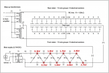
If you are using a typical multiplier section, you can change the voltage by just moving the charging resistor connection to a different point on the ladder. For example, if your multiplier section looks similar to CharlieM’s(attached pic), you can just move the connection of R13 to different nodes in the multiplier to step up or down in voltage.to test it my idea is to connect the different secondary of a transformer to a single secondary of another transformer... I do not know other ways .....
As Wrinex mentioned, you need to have the connection from the HV supply thru the step-up transformer to the stators in place for the diaphragm to charge up properly.
If you have a measurement setup, you can also take near field measurements to see the diaphragm resonance shift as you increase bias voltage. If mechanical stability of your ESL is low(large unsupported width and minimal tension), you will see resonance shift increasingly downward as instability is approached and the diaphragm gets "sucked" to one stator. If mechanical stability is high(small unsupported width and high tension) you may not see the resonance frequency shift much at all before you hear hissing or crackling indicating the ionization limit has been reached.
Diaphragm Resonance change with HV bias
Attachments
Highly recommended reading… I have also read into Borwick's "Loudspeaker etc. handbook" and section 3.2.7 addresses this from a theoretical (and slightly practical) point of view.

If you have control over the transformer step-up ratio and amplifier output voltage, you can use Baxandall’s recommendations in Section 3.2.9 to maximize peak output capability for your panel. More details on this topic here: Measured my ESL attempt
- If your transformer/amplifier combination generates less than the optimum stator voltages defined by Baxandall, increasing bias voltage above the “optimum” value will be beneficial; resulting in higher sensitivity and increased maximum SPL.
- If your transformer/amplifier combination can generate the optimum stator voltages, increasing bias voltage above the “optimum” value will also result in higher sensitivity but maximum SPL will be reduced.
@bolserst: Hi & thanks again for your feedback ... I am slowly reading into Baxandall's section in the loudspeaker book and reckon that it will take some time to digest as I do not have that much time for this currently ...
Interesting with your "upping" the bias voltage by 20 - 30% relative to the "optimal" value (the link you posted) ... As you know I am interested in gaining as much sensitivity as SQ allows and thus in due time I hope to arrive at a quite stable and precise design which supports a high sensitivity so interesting with this link, thanks!
Hope life is well ...
Cheers, Jesper
... I am slowly reading into Baxandall's section in the loudspeaker book and reckon that it will take some time to digest as I do not have that much time for this currently ... Interesting with your "upping" the bias voltage by 20 - 30% relative to the "optimal" value (the link you posted) ... As you know I am interested in gaining as much sensitivity as SQ allows and thus in due time I hope to arrive at a quite stable and precise design which supports a high sensitivity so interesting with this link, thanks!
Hope life is well ...
Cheers, Jesper
- Status
- This old topic is closed. If you want to reopen this topic, contact a moderator using the "Report Post" button.
- Home
- Loudspeakers
- Planars & Exotics
- there's a way to understand the limit of hv bias?