Hi i wondered if someone could help me out with this style of filter. which should allow me to segmented a planar speaker. but somehow i cant get it to work
the filter looks like this

I used this calculator
Low Pass Filter Calculator
When i use the resistance of the segment it self (2 Ohm) and a a frequency of 5000hz
output should be down 12dB at 20khz. the calculator gives me a cap value of 15.9uF
but i cant see hardly any attenuation at 20 khz. am i doing something wrong ?
the schematic would be the same as putting the cap paralel to the segment or am i missing something ?
the cool thing was if this would work you can divide your planar just like a segmented ESL and achieve good dispersion. particular interesing when mid/high freq range panels woud be used with the same wire
the filter looks like this
I used this calculator
Low Pass Filter Calculator
When i use the resistance of the segment it self (2 Ohm) and a a frequency of 5000hz
output should be down 12dB at 20khz. the calculator gives me a cap value of 15.9uF
but i cant see hardly any attenuation at 20 khz. am i doing something wrong ?
the schematic would be the same as putting the cap paralel to the segment or am i missing something ?
the cool thing was if this would work you can divide your planar just like a segmented ESL and achieve good dispersion. particular interesing when mid/high freq range panels woud be used with the same wire
Last edited:
Hi
Its a first-order low-pass filter with cut-off frequency of 5 kHz - exactly as you expected - but only when unloaded. In use it will depend on the load impedance - that has to be included in parallel with the capacitor.
yes but for instance my planar is 2 ohm, i could fill in the 2 ohms of the planar ad a cap parallel to it and should end up with a lowpass @ 5khz? but somehow thats not hapening. do i need a polarized cap ? or something impedance should be pretty stable with a planar speaker.
Last edited:
Hi
with a 2 ohm load, the two resistors form a voltage divider with an output impedance of 1 ohm - hence Vout is halved and cut-off frequency moves to 10 kHz. It also occurs to me that the equivalent series resistance (ESR) of the capacitor may not be low enough to give the attenuation you're seeking.
with a 2 ohm load, the two resistors form a voltage divider with an output impedance of 1 ohm - hence Vout is halved and cut-off frequency moves to 10 kHz. It also occurs to me that the equivalent series resistance (ESR) of the capacitor may not be low enough to give the attenuation you're seeking.
oh wait i have to add a resistor to ? i thought it would use the resistor of the panel itself.  to bad ive seen someone using this in there fullrange. but that was a drawing. im not sure if it ever worked properly. i want to divide my panel in a 2.6 ohm part and a 1 ohm part. and i would like to cut of the high frequency of the 2.6 ohm part, any pointers on how i could manage that without the normal coil. since that would not allow me to still put it in series
to bad ive seen someone using this in there fullrange. but that was a drawing. im not sure if it ever worked properly. i want to divide my panel in a 2.6 ohm part and a 1 ohm part. and i would like to cut of the high frequency of the 2.6 ohm part, any pointers on how i could manage that without the normal coil. since that would not allow me to still put it in seriesi want to divide my panel in a 2.6 ohm part and a 1 ohm part. and i would like to cut of the high frequency
of the 2.6 ohm part, any pointers on how i could manage that without the normal coil. since that would not
allow me to still put it in series
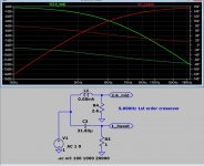
Is this what you want to do? Panel crossover
The HF load is only 1R, so it's a pretty bad amp load.
Last edited:
You can use LTSpice with the R-L-C measurements on your panels. For the crossovers, you will need to hand-build the low inductance value, low resistance inductors using a good quality LRC meter.
When you use a microphone to measure SPL and phase vs. frequency of your prototype speaker you can switch to XSIM and also include baffle and room effects.
When you use a microphone to measure SPL and phase vs. frequency of your prototype speaker you can switch to XSIM and also include baffle and room effects.
Attachments
Is this what you want to do? Panel crossover
The HF load is only 1R, so it's a pretty bad amp load.
yes this is the setup. so up to 5khz it would see 3.6 ohm and above 1 ? ohm ?
The thing is the panel will be bigger so these numbers are just for ilustration 1 Ohm is not very high
but i tried this setup and t somehow the drop is not there i should recheck if im not doing something wrong.You can use LTSpice with the R-L-C measurements on your panels. For the crossovers, you will need to hand-build the low inductance value, low resistance inductors using a good quality LRC meter.
When you use a microphone to measure SPL and phase vs. frequency of your prototype speaker you can switch to XSIM and also include baffle and room effects.
yes this is a normal crossover, problem is the tweeter wont contribute in the low end this way.
i would like to create a setup like in an esl that only parts are filtered with a lowpass and one part is playing fullrange, all in series would be ideal. else i might use only one coil to filter. and put one part fullrange parallel before the coil. if the impdance is high enough it is doable.yes this is the setup. so up to 5khz it would see 3.6 ohm and above 1 ? ohm ?
The time constant is set by the two resistors in parallel.
So then f = 1 / [2Pi x Rp x C] where Rp = R1 x R2/[R1 plus R2]
- Status
- This old topic is closed. If you want to reopen this topic, contact a moderator using the "Report Post" button.
- Home
- Loudspeakers
- Planars & Exotics
- Equation about RC filters for planar use