Hi WrineX
I tried moving away the microphones, both the Umik and the Technics, to have a SPL 10 dB less, but oddly the THD seems a little higher. I've been trying to find out if there's something around responsible for the phenomenon, but I have not found anything. As I said in the post above I will come back to the topic when I get the new ribbons
I was trying to tell that I had a umik that was 10 dB of I the high freq. So if you got any other mic to check if it is working correct ? I should.
I was trying to tell that I had a umik that was 10 dB of I the high freq. So if you got any other mic to check if it is working correct ? I should.
Sorry wrineX, some phrases google translate it very badly. If now I understand you had a UMIK wrong 10 dB in high frequency. My umik seems OK: Compared to both the Tecnics (on which I mounted the kecg2742 capsule) and the electret capsules KECG2742 and MCE4000 on my assemblies the differences on the shape of the SPL are contained within a couple of dB, and the same is for the THD. Of course, the absolute value of the SPL is different for the different microphones, since only the umik is calibrated but the frequency-dependent trend is very similar. When I connected the umik I immediately loaded the calibration file.
Sorry wrineX, some phrases google translate it very badly. If now I understand you had a UMIK wrong 10 dB in high frequency. My umik seems OK: Compared to both the Tecnics (on which I mounted the kecg2742 capsule) and the electret capsules KECG2742 and MCE4000 on my assemblies the differences on the shape of the SPL are contained within a couple of dB, and the same is for the THD. Of course, the absolute value of the SPL is different for the different microphones, since only the umik is calibrated but the frequency-dependent trend is very similar. When I connected the umik I immediately loaded the calibration file.
Aaah ok
") then forget what i said
then forget what i said It's been a long time since my last post, but I've been busy building the engine:
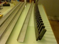
First I realized the structure of the back magnetic field closure. As with the short ribbon, I do not make a continuous structure, to avoid resonances, but use 10x15mm section bars, spaced by a 26mm pitch, with the 10mm side welded to the 6x25x112mm bar behind the magnets. In total to have a section equivalent to that of the simulation I have to cut 180 short pieces (vertical) + 90 long (horizontal) pieces. The hard part is to weld them in the right position, because the retraction of the cooling metal always deforms the structure. I built a mask to keep the pieces in place during the welding, but anyway I even found some errors of 1 mm. I also underestimated the deformation of the metal caused by welds. The bars have curved much more than expected, and, worse, the overall curvature is given by the sum of many small local curvatures, so I've had a lot to work to straighten out.
after welding.JPG
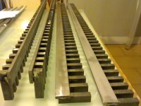
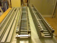
After a first straightening of the bars, in order to remove the local deformations I have skinned the surface facing the magnets by grinding with diamond paste and after much work I was satisfied with a good result.
iron bars straightened.JPG
I planned to stick the transverse bars on one side with welding, and on the other with M4 screws.
First I made threaded holes (88!) And through holes, then assembled the structure by holding it together with thicknesses and clamps, so that the short welded bars can be leveled, then I fastened the transverse bars with the screws, and finally I weld them on the other side.
To avoid deformation of the structure under the action of the magnetic field I put 3 cylinders of aluminum spaced about 30 cm.
To support the clamps for electrical connections, I welded 2 mm thick stainless steel angular sections at the ends of the long bars. On these are attached, with screws, aluminum bars of section 5x15 mm, which are the bases for clamps.
iron structure.JPG
First I realized the structure of the back magnetic field closure. As with the short ribbon, I do not make a continuous structure, to avoid resonances, but use 10x15mm section bars, spaced by a 26mm pitch, with the 10mm side welded to the 6x25x112mm bar behind the magnets. In total to have a section equivalent to that of the simulation I have to cut 180 short pieces (vertical) + 90 long (horizontal) pieces. The hard part is to weld them in the right position, because the retraction of the cooling metal always deforms the structure. I built a mask to keep the pieces in place during the welding, but anyway I even found some errors of 1 mm. I also underestimated the deformation of the metal caused by welds. The bars have curved much more than expected, and, worse, the overall curvature is given by the sum of many small local curvatures, so I've had a lot to work to straighten out.
after welding.JPG
After a first straightening of the bars, in order to remove the local deformations I have skinned the surface facing the magnets by grinding with diamond paste and after much work I was satisfied with a good result.
iron bars straightened.JPG
I planned to stick the transverse bars on one side with welding, and on the other with M4 screws.
First I made threaded holes (88!) And through holes, then assembled the structure by holding it together with thicknesses and clamps, so that the short welded bars can be leveled, then I fastened the transverse bars with the screws, and finally I weld them on the other side.
To avoid deformation of the structure under the action of the magnetic field I put 3 cylinders of aluminum spaced about 30 cm.
To support the clamps for electrical connections, I welded 2 mm thick stainless steel angular sections at the ends of the long bars. On these are attached, with screws, aluminum bars of section 5x15 mm, which are the bases for clamps.
iron structure.JPG
Attachments
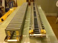
At this point I disassembled the structures and on each bar I put magnets, NdFeB N38 25x25x5mm, and polar pieces, which are held only by friction without glue. It was pretty simple.
The assembly of the structure with the magnets, on the other hand, was by no means simple, and I regretted not having followed the same type of prototype construction, that is with the transverse bars fixed with screws on both sides. In fact, with that type of construction, the two parts with the magnets could be approached, first placing a thickness in the middle, without problems, and then they could fix the transverse bars by screws one by one, so the magnetic field was closed step by step. Instead, having soldered all the transverse bars on one side to halve the thread count, as soon as I approached the two sides they were drawn violently with my hand in the middle. It was not pleasant, but fortunately I only brought a couple of small holes. Then I improved the technique and went all smooth.
motors finished.JPG
The wooden blocks that are seen below the polar expansions are used to keep them in place during the work. In fact, as the structure weighs 17 Kg, by dropping it on the table, magnet down, the polar pieces may slip out of place.The other wooden blocks that are seen on the sides of the clamps for connections are used to close the air passages at the ends of the ribbon. A job as a chaser! Now the 2 engines are over and "only" ribbons and return wires remain
Attachments
After a long time I'm back here. I apologize to all those who followed this thread for the long interruption, but for about 1 year I had personal problems, then I resumed my hobby but for a long time without satisfactory results. I will try to summarize the most interesting passages and problems encountered. I hang up on the last post and then describe the significant points of my experiences.
For the return conductors I used at the beginning rigid round copper wires of section 6 mm ^ 2 fixed with small wooden dowels inside the iron structure, in positions where the simulation of the magnetic field gave me a low value, of about 0.03 T
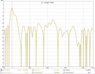
According to the simulations with Unibox, to obtain what I wanted it was necessary that the moving mass of the ribbon was greater than 8 g, and given that the sensitivity is inversely proportional to the electrical resistance and to the square of the mass, in order not to lower the SPL too much I have made the first attempts with Alu 80 um thick, which with the 25 cm short ribbons had given me good results (but on a 30 cm short ribbon the parasitic inductances are much less). The first ribbon, L1, I made it similar to the short one that had given me good results: The lateral suspensions were made of 12 g / m ^ 2 model aircraft paper impregnated with shore 90 polyurethane rubber. The terminal suspensions had a fold U shaped bridged at the top with 200um thick silicone rubber. I had divided the Alu into 3 strips held together by 3mm depron to stiffen the tape and I had tinned the ends for good electrical contact. At the ends of the ribbon, where depron was missing, the 3 strips were kept together with glued paper.
ribbon L1 (10) free air, umik not cal at 5 cm
This curve and many other subsequent ones are not calibrated in level because only recently, when I started to pay attention to the levels, I realized that something was wrong, and I discovered that, using REW, to have UMIK calibrated it was necessary to set in the preferences "input microphone ", while I had set" input default ", and therefore the levels depended on the volume adjustment of the input of the sound card.
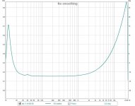
The contacts on the clamps are made with copper strips, golden plated, 100um thick. The overall resistance measured with the 4-wire method in d.c. it is 0.16 ohms and this is the impedance curve
ribbon L1 (5)
For the return conductors I used at the beginning rigid round copper wires of section 6 mm ^ 2 fixed with small wooden dowels inside the iron structure, in positions where the simulation of the magnetic field gave me a low value, of about 0.03 T
According to the simulations with Unibox, to obtain what I wanted it was necessary that the moving mass of the ribbon was greater than 8 g, and given that the sensitivity is inversely proportional to the electrical resistance and to the square of the mass, in order not to lower the SPL too much I have made the first attempts with Alu 80 um thick, which with the 25 cm short ribbons had given me good results (but on a 30 cm short ribbon the parasitic inductances are much less). The first ribbon, L1, I made it similar to the short one that had given me good results: The lateral suspensions were made of 12 g / m ^ 2 model aircraft paper impregnated with shore 90 polyurethane rubber. The terminal suspensions had a fold U shaped bridged at the top with 200um thick silicone rubber. I had divided the Alu into 3 strips held together by 3mm depron to stiffen the tape and I had tinned the ends for good electrical contact. At the ends of the ribbon, where depron was missing, the 3 strips were kept together with glued paper.
ribbon L1 (10) free air, umik not cal at 5 cm
This curve and many other subsequent ones are not calibrated in level because only recently, when I started to pay attention to the levels, I realized that something was wrong, and I discovered that, using REW, to have UMIK calibrated it was necessary to set in the preferences "input microphone ", while I had set" input default ", and therefore the levels depended on the volume adjustment of the input of the sound card.
The contacts on the clamps are made with copper strips, golden plated, 100um thick. The overall resistance measured with the 4-wire method in d.c. it is 0.16 ohms and this is the impedance curve
ribbon L1 (5)
Attachments
The drop at 20 KHz compared to 40 Hz is just under 20 dB, about 7 dB greater than that due to inductance alone. After many tests I found out why: Those lateral suspensions raised the response below a few thousand Hz leaving the SPL at 10-20 KHz unchanged, and the result was a more descending than expected graph taking into account only the inductance. Checked with a test ribbon with Al 36 um thick, and lateral suspensions made in the same way with 12g / m ^ 2 impregnated paper:
try alu 36 um
I had to find another material for the side suspensions that didn't give that inconvenience. Furthermore, it was evident that the Alu 80 um thick, having a low resistance with respect to the impedance of the series inductance would in any case limit the response on the HF. However I wanted to try other tapes with that thickness before moving on to thinner Alu
Before I put that tape aside, as it bothered me to increase the distortion below 60 Hz, I tried several changes to decrease it, but with little success. I got this curve by making many cross cuts on the depron:
L1 (18), free air, umik not cal at 6 cm
The impulse response was not bad. The moving (calculated) mass was about 13g
L1 (18) imp
In trying other changes I have irreparably destroyed the ribbon.
Attachments
Last edited:
Another ribbon, L3, I made it again with 80 um aluminum, but stiffer and therefore also heavier: Instead of the 3mm thick depron I glued on the aluminum strips a strip of extruded foam 10 mm thick. The extruded foam is similar to the depron but lighter (30 Kg / m ^ 3 instead of 40), but also less rigid with the same thickness. However, with the thicknesses I mentioned above, the extruded foam was much stiffer than the depron.
I still made the lateral suspensions with 12g / m ^ 2 paper but impregnated with shore 40 polyurethane rubber. Otherwise it was like L1.
L3 (1) (free air, umik not cal at 6 cm)
The distortion below 40 Hz is definitely one of the best I have had. I liked it, but the impulsive response was a toilet. The total weight of the tape was 23.7g and the moving mass was 18g
Subsequently, to decrease the parasitic inductance, I replaced the return conductors with a circular section with copper strips 0.1 x 20 mm glued on the pole pieces. I found that putting them where the magnetic field is strong does not cause inconveniences, and the parasitic inductance has decreased considerably, making me gain more than 4 dB at 20 KHz. However, I left the 80 um Alu and moved to 36 um.
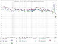
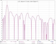
A curiosity that may interest someone: Among others I made a tape (L11), with 36 um aluminum glued on 10 mm thick extruded foam, which had a very pronounced peak in the response at just under 20 KHz (blue curve).
L11_2
I reduced the thickness of the extrusion to 5mm and the peak disappeared (red curve). Imagining that it had gone out of band, I weighted the extruded surface with paint and 2 lower peaks (green curve) appeared, always around 20 KHz. Since that peak also appeared in other sizes but only on ribbons with extruded 10 mm thick, my idea is that the extruded sounded in the thickness. Maybe it will be useful on another occasion, if you can dampen the Q.
I still made the lateral suspensions with 12g / m ^ 2 paper but impregnated with shore 40 polyurethane rubber. Otherwise it was like L1.
L3 (1) (free air, umik not cal at 6 cm)
The distortion below 40 Hz is definitely one of the best I have had. I liked it, but the impulsive response was a toilet. The total weight of the tape was 23.7g and the moving mass was 18g
Subsequently, to decrease the parasitic inductance, I replaced the return conductors with a circular section with copper strips 0.1 x 20 mm glued on the pole pieces. I found that putting them where the magnetic field is strong does not cause inconveniences, and the parasitic inductance has decreased considerably, making me gain more than 4 dB at 20 KHz. However, I left the 80 um Alu and moved to 36 um.
A curiosity that may interest someone: Among others I made a tape (L11), with 36 um aluminum glued on 10 mm thick extruded foam, which had a very pronounced peak in the response at just under 20 KHz (blue curve).
L11_2
I reduced the thickness of the extrusion to 5mm and the peak disappeared (red curve). Imagining that it had gone out of band, I weighted the extruded surface with paint and 2 lower peaks (green curve) appeared, always around 20 KHz. Since that peak also appeared in other sizes but only on ribbons with extruded 10 mm thick, my idea is that the extruded sounded in the thickness. Maybe it will be useful on another occasion, if you can dampen the Q.
Attachments
The first ribbon that gave me, overall and in my opinion, good results was L14, made like this: 4 strips aluminum 36 um thick, the 2 central 7mm wide and the 2 lateral 5mm (27mm total including the gap) glued on extruded foam 5x24x1080 mm, painted with heavy paint. For the side suspensions I did not use the usual paper but very light fabric (40g / m ^ 2) impregnated with acetic silicone rubber both to make them take the round shape and to airtight it. The total weight was around 18g, and the moving mass I estimated was 15g
L14 (13)
The distortion was low even at LF and the impulsive response was not bad, even compared to that of the last ribbon I made with 10 um alu that I will publish later. I think in the future I will repeat this ribbon with appropriate changes.
I also tried to change the longitudinal tension of the ribbon, and the result is: more tension = more distortion at BF. So I keep the terminal suspensions completely slow and I entrust the maintenance of the ribbon position to the lateral suspensions only.
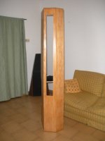
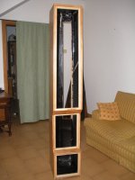
At this point I decided it was time to build the box and try to put the speaker with the L14 ribbon on it. Then put the speaker aside I turned into a carpenter and after a couple of months here is the result (right box, left is symmetric)
box, front
box, rear
L14 (13)
The distortion was low even at LF and the impulsive response was not bad, even compared to that of the last ribbon I made with 10 um alu that I will publish later. I think in the future I will repeat this ribbon with appropriate changes.
I also tried to change the longitudinal tension of the ribbon, and the result is: more tension = more distortion at BF. So I keep the terminal suspensions completely slow and I entrust the maintenance of the ribbon position to the lateral suspensions only.
At this point I decided it was time to build the box and try to put the speaker with the L14 ribbon on it. Then put the speaker aside I turned into a carpenter and after a couple of months here is the result (right box, left is symmetric)
box, front
box, rear
Attachments
Last edited:
I made the first tests as soon as the first crate was finished, which therefore could not be airtight. All the walls were covered with 4 cm sponge, and in addition I had put some sponge shelves to dampen the resonances related to the height. Here is the effect of the box on the curve
L14 (11 & 13)
Raising the response from 40 to about 500 Hz is typical of ribbons with impregnated side suspensions or, to understand each other, made with material through which it is difficult to blow, and I was able to notice it with all the similar ribbons that I put in box later. I insisted a bit with several ribbons before understanding the problem, so I later tried to use a material with the right porosity
I abandoned the paper because, if not impregnated, over time it loses its shape and the ribbon moves, and I tried with polyester fabrics. This is a thermoformable material, so I could shape it with heat in a few minutes without having to wait 2 days for the impregnation to cure properly
Someone will think "but why don't you try a regular tape without lateral suspensions?". I thought so too and so I made some attempts. This is a 42mm wide ribbon, 4 Alu 36um thick strips 9,10,10,9 mm wide glued on extruded foam 5x36x1100mm, gap towards polar expansions about 1,5mm, in a closed case full of sponge
L18 (3)
BF distortion is not acceptable. By reducing the width of the side strips by 3.5mm, then the total width to 35mm, the gaps towards the polar expansions become 5mm and the distortion at BF is reduced a little, but in absolute it is still high, apart from other drawbacks
L18 (4)
I have tried, without lateral suspensions, also other tapes, pleated, or embossed, one single or more strips, with and without substrate, etc. but with disappointing results
Attachments
Last edited:
As said in the previous post I went back to the ribbons with lateral suspensions.
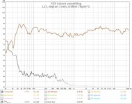
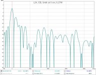
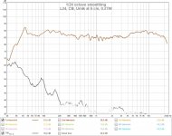
Another ribbon that had little LF distortion was L23, so made: 4 alu 36 um strips, 5,7,7 and 5 mm wide, glued on 3 mm thick depron with lateral suspensions of 70g / m ^ 2 polyester chiffon, in closed box with sponge only on walls, Umik calibrated to 6 cm, 0,3W
L23 (16)
L23 (16) _imp
The curve is not flat enough, but the THD remains low up to 40Hz.
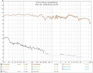
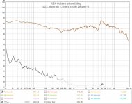
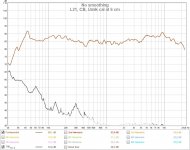
Later I reduced the thickness of the depron from 3 to 1.5 mm and I changed the side suspensions with another polyester fabric, with a narrower and much lighter (28g / m ^ 2) and softer texture, to lower the Resonance Fr. I measured the response only in open air, with Umik calibrated at 6 cm and 0.3W
L23_1 (15)
The 40 Hz THD is even lower, but of course this is due to the absence of the closed box, and the impulsive response has worsened
L23_1 (15) _imp
A remarkable and positive fact in ribbons with alu 36 um is that the fall at 20 KHz is much more contained than the ribbons with alu from 80 um, and in some ribbons even lower than the fall calculated on the basis of parasitic inductance.
Another ribbon that had little LF distortion was L23, so made: 4 alu 36 um strips, 5,7,7 and 5 mm wide, glued on 3 mm thick depron with lateral suspensions of 70g / m ^ 2 polyester chiffon, in closed box with sponge only on walls, Umik calibrated to 6 cm, 0,3W
L23 (16)
L23 (16) _imp
The curve is not flat enough, but the THD remains low up to 40Hz.
Later I reduced the thickness of the depron from 3 to 1.5 mm and I changed the side suspensions with another polyester fabric, with a narrower and much lighter (28g / m ^ 2) and softer texture, to lower the Resonance Fr. I measured the response only in open air, with Umik calibrated at 6 cm and 0.3W
L23_1 (15)
The 40 Hz THD is even lower, but of course this is due to the absence of the closed box, and the impulsive response has worsened
L23_1 (15) _imp
A remarkable and positive fact in ribbons with alu 36 um is that the fall at 20 KHz is much more contained than the ribbons with alu from 80 um, and in some ribbons even lower than the fall calculated on the basis of parasitic inductance.
Attachments

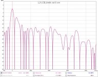
At this point it was time to make a choice, among the ribbons already made, of one to put in the box and to duplicate to make the stereo. I have been undecided for a long time: It was a matter of choosing between a low LF distortion and a good impulsive response and in the end I opted for the second. Among the others I had made a ribbon with 10 um aluminum, 4 strips 5, 7.5, 7.5, 5 mm wide glued on 12 g / m ^ 2 paper and lateral suspensions made with unimpregnated 30 g / m ^ 2 polyester chiffon . Total weight 5.6g and calculated moving mass 3g. Put in the closed box he had this answer
L21_1 (13)
L21_1 (13) imp
As I said in a previous post, now, reviewing the measurements of L14, I have the doubt that I could have done better with 36 um alu, but for the moment the choice is made and I will think about it later, after having enjoyed a bit 'my new speakers.
In making the second box, as I remained the researcher mentality, I was unable to resist the temptation to make a variant in the engine. I had already made the second engine the same as the first, but I disassembled it and replaced the pole pieces made as in the photo of post 47 with others of iron of the same thickness but flat, without bolts. So the intensity of the magnetic field is no longer uniform within a few% but has the usual trend of flat polar expansions (verified with a hall probe). I wanted to see if indeed a non-uniform field affects THD at LF, and even if the rostrums were responsible for some irregularity in the response. Made another ribbon equal to L21, placed in the second engine and put it all in the closed twin box, the results are these
L24_1 (5)
L24_1 (5) imp
Attachments

At this point it was time to make a choice, among the ribbons already made, of one to put in the box and to duplicate to make the stereo. I have been undecided for a long time: It was a matter of choosing between a low LF distortion and a good impulsive response and in the end I opted for the second. Among the others I had made a ribbon with 10 um aluminum, 4 strips 5, 7.5, 7.5, 5 mm wide glued on 12 g / m ^ 2 paper and lateral suspensions made with unimpregnated 30 g / m ^ 2 polyester chiffon . Total weight 5.6g and calculated moving mass 3g. Put in the closed box he had this answer
L21_1 (13)
L21_1 (13) imp
As I said in a previous post, now, reviewing the measurements of L14, I have the doubt that I could have done better with 36 um alu, but for the moment the choice is made and I will think about it later, after having enjoyed a bit 'my new speakers.
In making the second box, as I remained the researcher mentality, I could not resist the temptation to make a variant in the engine. I had already made the second engine the same as the first, but I disassembled everything and replaced the pole pieces made as in the photo of post 47 with others of iron of the same thickness but flat, without bolts. So the intensity of the magnetic field that was uniform within a few% now has the usual trend of flat polar expansions (verified with a hall probe, about 20% on the +/- 8mm excursion of the ribbon). I wanted to see if actually a non-uniform field affects THD at LF, and even if the rostrums were responsible for some irregularity in the response. Made another ribbon equal to L21, put it in the second engine and put it all in the twin closed box, the results are these
L24_1 (5)
L24_1 (5) imp
Attachments


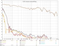
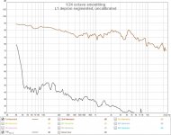
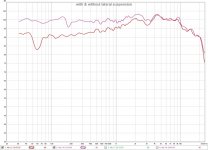
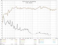
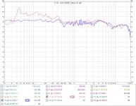
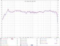
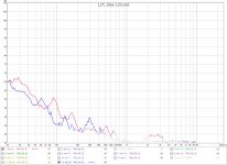
Comparing the graphs, the SPL is in some places a little higher in L24, and this is partly due to the fact that the DC resistance of L24 is a few% lower than L21, while the test voltage was the same ( 0.26W on L21 and 0.27W on L24) and partly due to positioning error of the microphone.
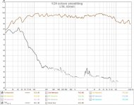
L21 & L24
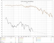
L21 & L24, THD
the THD at LF is only a little higher in the speaker with less uniform magnetic field (L24), and the irregularities in the response are almost equal. Only around 20 KHz does the ribbon in the motor without bolts (L24) give a couple of dB more than L21. I expected a slightly higher THD to LF, but perhaps there is a compensation, due to the fact that these LF ribbons move transversely arching in both motors, despite the central strips being wider than the lateral ones. So in the motor with less uniform magnetic field, where the intensity of the magnetic field is minimal in the center, the ribbon should arch less. I say should because I have not noticed differences between the two ribbons seen with the stroboscope. The movement of the ribbons in the longitudinal direction is instead almost pistonic.
It was a question I had to solve, and it cost me a lot of effort to change the engine. At this moment I don't think I'll repeat the work to put it back as before.
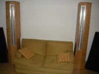
In the end I have the 2 boxes with the ribbons. Only the front covers are missing
boxes front
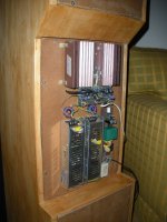
On the back there are the amplifier and the power supplies, still without the protection grille
amp + power supply
At this point it would be customary for me to write a few lines about listening impressions, but I can't praise the things I do myself, so I'll skip this part. However it is my personal conviction, dictated by my previous listening experiences and confirmed by these speakers, that the sound coming from a single transducer has some peculiarities that cannot be equaled by a manychannel made with two or more spatially separated transducers, both phased arrays or with digital filters, and however crossings are made. If then the only transducer is a ribbon I leave you to imagine the result.
Finally I want to thank all those who have published their works on this forum, because they have been a stimulus and teaching for me.
L21 & L24
L21 & L24, THD
the THD at LF is only a little higher in the speaker with less uniform magnetic field (L24), and the irregularities in the response are almost equal. Only around 20 KHz does the ribbon in the motor without bolts (L24) give a couple of dB more than L21. I expected a slightly higher THD to LF, but perhaps there is a compensation, due to the fact that these LF ribbons move transversely arching in both motors, despite the central strips being wider than the lateral ones. So in the motor with less uniform magnetic field, where the intensity of the magnetic field is minimal in the center, the ribbon should arch less. I say should because I have not noticed differences between the two ribbons seen with the stroboscope. The movement of the ribbons in the longitudinal direction is instead almost pistonic.
It was a question I had to solve, and it cost me a lot of effort to change the engine. At this moment I don't think I'll repeat the work to put it back as before.
In the end I have the 2 boxes with the ribbons. Only the front covers are missing
boxes front
On the back there are the amplifier and the power supplies, still without the protection grille
amp + power supply
At this point it would be customary for me to write a few lines about listening impressions, but I can't praise the things I do myself, so I'll skip this part. However it is my personal conviction, dictated by my previous listening experiences and confirmed by these speakers, that the sound coming from a single transducer has some peculiarities that cannot be equaled by a manychannel made with two or more spatially separated transducers, both phased arrays or with digital filters, and however crossings are made. If then the only transducer is a ribbon I leave you to imagine the result.
Finally I want to thank all those who have published their works on this forum, because they have been a stimulus and teaching for me.
Attachments
Threads / projects / people behind work like this, amaze me.
My *experience* is (~40 years) building amps (mostly)
building *box* speakers, is an art (I feel beyond me?)
building drivers, is like building an elaborate aircraft,
building *exotic* drivers, like build a space ship.
KUDOS brother, keep up the outstanding work!!!
My *experience* is (~40 years) building amps (mostly)
building *box* speakers, is an art (I feel beyond me?)
building drivers, is like building an elaborate aircraft,
building *exotic* drivers, like build a space ship.
KUDOS brother, keep up the outstanding work!!!
- Home
- Loudspeakers
- Planars & Exotics
- my ribbons full range in CB