Hello everyone
For a long time, I've been pursuing the idea of building a full range speaker (I think that's the same for many of you: it's a worthy target without a definite solution). After my first experiences with the AMTs I thought this was the right configuration, so I made many accounts and several AMT achievements. Unfortunately (I say unfortunately because I took a lot of time) I realized that the solutions to have good low at levels around 100 dB are antithesical to the solutions to have good highs, and no acceptable compromise can be found. So I went to the ribbon drivers, or, to be more precise, to almost ribbons.
Not everything that follows is a preliminary study. Much has emerged during the constructions which at the moment are at the end of the first phase, building a shorter ribbon.
Other points I have set are:
1) Put the driver in a closed box of non-prohibitive dimensions, possibly 100 liters, max 200, which already limits the design.
2) Maximum air volume displaced between 200 and 300 cm ^ 3 peak
3) efficiency will naturally be low but I would be happy to put in my room 100 dB with 100W
I started to make a few accounts on the Vas parameter, which in my case seemed to me very important, and combining well know equations I get:
Vas = 10,35*Sd^2/(Fs^2*Mms)
As with other factors, the volume of the box must be proportional to Vas and, according to the equation, to limit the volume of the box Sd must be small and Mms large. However, if I make small Sd, to have the same amount of air moved I need to increase Xp (this is one of the reasons why the AMT solution did not work). By fixing for Xp the acceptable value = 8mm, Sd is determined between 250 and 375 cm ^ 2. To get an idea of the quantum of Mms I put Fs = 25 Hz, Sd = 300 cmq, Vas = 170 liters and get Mms = 30 grams !!! Much above any ribbon. The target set seems unattainable, but I do not win for it, and armed with UniBox software I try some simulation, and I realize right away that I have to quantify the parameter Bl. Then I take the "Magnet" software and start drawing the motor.
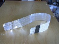
One step back: A real ribbon in a closed box is a contradiction, due to side gaps. So I have to close "air-tight" the slots and I thought of doing it with 12g / m ^ 2 airmodel paper strips impregnated with silicone rubber and shaped like a suspension of a cone woofer.
The length of the ribbon I fixed at the first to 92.5 cm, since to make it longer would be a problem for me because the line I have is 100cm long. The width I initially fixed at 4 cm so that the geometric surface is 370 cm ^ 2. For the side suspensions I keep a space of 8mm per side, so in total the magnetic gap should be 56 mm wide.
Then I come back to "magnet" and make a lot of simulations. The target is (of course): the highest possible field and, priority condition, uniform throughout the area as a premise for having low THD. Immediately touch with my hands what you all already know: by increasing the width of the gap over 20 mm, the field strength decreases rapidly and at the same time degrades uniformity. While the intensity is issue of the volume of the magnets employed (I want to keep it to a minimum, being a little shred), for the uniformity after a lot of work I arriving at an acceptable design
For a long time, I've been pursuing the idea of building a full range speaker (I think that's the same for many of you: it's a worthy target without a definite solution). After my first experiences with the AMTs I thought this was the right configuration, so I made many accounts and several AMT achievements. Unfortunately (I say unfortunately because I took a lot of time) I realized that the solutions to have good low at levels around 100 dB are antithesical to the solutions to have good highs, and no acceptable compromise can be found. So I went to the ribbon drivers, or, to be more precise, to almost ribbons.
Not everything that follows is a preliminary study. Much has emerged during the constructions which at the moment are at the end of the first phase, building a shorter ribbon.
Other points I have set are:
1) Put the driver in a closed box of non-prohibitive dimensions, possibly 100 liters, max 200, which already limits the design.
2) Maximum air volume displaced between 200 and 300 cm ^ 3 peak
3) efficiency will naturally be low but I would be happy to put in my room 100 dB with 100W
I started to make a few accounts on the Vas parameter, which in my case seemed to me very important, and combining well know equations I get:
Vas = 10,35*Sd^2/(Fs^2*Mms)
As with other factors, the volume of the box must be proportional to Vas and, according to the equation, to limit the volume of the box Sd must be small and Mms large. However, if I make small Sd, to have the same amount of air moved I need to increase Xp (this is one of the reasons why the AMT solution did not work). By fixing for Xp the acceptable value = 8mm, Sd is determined between 250 and 375 cm ^ 2. To get an idea of the quantum of Mms I put Fs = 25 Hz, Sd = 300 cmq, Vas = 170 liters and get Mms = 30 grams !!! Much above any ribbon. The target set seems unattainable, but I do not win for it, and armed with UniBox software I try some simulation, and I realize right away that I have to quantify the parameter Bl. Then I take the "Magnet" software and start drawing the motor.
One step back: A real ribbon in a closed box is a contradiction, due to side gaps. So I have to close "air-tight" the slots and I thought of doing it with 12g / m ^ 2 airmodel paper strips impregnated with silicone rubber and shaped like a suspension of a cone woofer.
The length of the ribbon I fixed at the first to 92.5 cm, since to make it longer would be a problem for me because the line I have is 100cm long. The width I initially fixed at 4 cm so that the geometric surface is 370 cm ^ 2. For the side suspensions I keep a space of 8mm per side, so in total the magnetic gap should be 56 mm wide.
Then I come back to "magnet" and make a lot of simulations. The target is (of course): the highest possible field and, priority condition, uniform throughout the area as a premise for having low THD. Immediately touch with my hands what you all already know: by increasing the width of the gap over 20 mm, the field strength decreases rapidly and at the same time degrades uniformity. While the intensity is issue of the volume of the magnets employed (I want to keep it to a minimum, being a little shred), for the uniformity after a lot of work I arriving at an acceptable design
Attachments
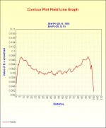
In the drawing, the magnets section, NdFeB, is 5 x 25 mm.
Field strength Bx along the diagonal -20.8 / 20, -8mm
Intensity of the Bx field along a central line
The intensity is really low, but the magnets are few and the non-uniformity is 17% peak to peak across the 40x16mm area where the ribbon will move, and 5% on the center line.
At this point I decide that because of the unknowns involved (especially on the side and terminal suspensions), I should first make some tests with a shorter construction, 25 cm instead of 92.5.
Then I resume the SW "UniBox" and do simulations with the Following parameters:
- Sd = 100 cm ^ 2 (4x25)
- Mms varies between 1.3 and 3.9 grams (this is an output parameter, not input, so indirectly imposed by Vas) 1.3 grams applies to Alu 10 um thick while 3.9 grams for Alu 80um. The extra weight with respect to Alu only takes into account non-conductive additional stuff.
- Re varies between 0.03 and 0.08 ohms, according to the thickness of Alu and the number of strips in which the ribbon will be divided
- Qms = 2, arbitrarily assumed value.
- Fs varies between 15 and 22 Hz, depending on the thickness of the aluminum
- Vas chosen so that with the setted Fs I get back the desired Mms
- Qes chosen so that in the output parameters I get back the conservative value B = 0.09T
- Xp = 8mm
- Vb = 40 liters, so that then with a 92.5 cm long ribbon I can use Vb = 150 liters
In fact, the above values are not entirely arbitrary, but I chose them after making some realizations and measuring the parameters.
I show the results of the 2 most significant simulations.
The first is for a ribbon with Alu 10um thick without strip division: Fs = 15Hz, Vas = 1500 liters, (which gives me the output Mms = 1.3 g) Re = 0.03 ohms, Qes = 5.5 , (which gives me the output Bl = 0.02Tm (25 cm long ribbon in 0.09T. I can not see the third decimal place))
resp10um corto.bmp
As expected, the F3 is too high, 56 Hz, so I try with Alu 80um and 4 strips: Fs = 21Hz, Vas = 250 liters, (which gives me the output Mms = 3.87 g), Re = 0.08 ohms, Qes = 5.5 (Which gives me the output Bl = 0.09Tm (100 cm in 0.09T)).
resp80um corto.bmp
The F3 is 35.3 Hz, and I think it might be fine.
I already feel someone's objections: But it sucks! A SPL of only 78 dB and then a peak on the low of 6 dB!
Advance Feedback:
--- The SPL assumed it would be low, but with 100W I would already give 98dB, and then when I make the longest ribbon I will have a few dB more. As a backup solution I can always double the volume of the magnets, then increase the SPL again and simultaneously lower the peak.
--- The peak I can easily kill it with equalization, or mechanical damping, or both with a small increase of F3.
At this point I can proceed with the realization. First the engine
Attachments
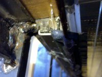
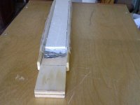
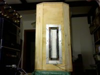
The schema of the simulation structure is that already illustrated, but in the realization I made sure that the iron that closes the magnetic field does not form a continuous channel, because in a first version made in that way I had problems with the resonances. So instead of making the lateral iron plates as long as the ribbon and 5 mm thick I did 10 U with fingers of section 8 x 15 mm.
rib short_rear.JPG
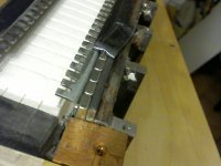
The polar expansions I got from a 1.5 mm U-bend sheet, diverging the top enough. As in the design, the U wings are slightly tapered, and above all to avoid shading the tape I practiced on them and throughout the length slits 3 x 8 mm with a pitch of about 7 mm.
rib short_magn.JPG
The plates on the back of the magnets are normal steel for building, 3 x 25 mm and 8 x 15 mm. I joined them together with welding. Even U vertical bars are welded, but only 6 per piece to have more room to work. The other 4 I proposed to add them later and keep them in situ with glue and magnetic attraction. Horizontal lower bars at the bottom of the U are instead held with screws, so they make easier to mount the magnets by dividing the structure into two parts . Then I saw on the SPL charts that adding the other non-welded bars I had only 1 dB more, so I did all the tests with only the 6 U welded. Unfortunately I did not make photos during the construction and now I have everything mounted, however if something is not clear I will help with the description.On the 3 x 25mm profile that comes into contact with the magnets, I have epoxy bonded on the short side a 1.2mm thick 5x1.5mm aluminum L strip, which serves as a jolt to hold the magnets on that side.
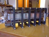
rib short_stop.JPG
To insert the magnets I prepared the two halves of the iron structure, removing the locking bars with screws. In this way I could insert magnets, 5x10x25, on one strip at a time. Then I gathered the two halves of the structure by helping me with a thick wood put in place of the ribbon. The magnets are fixed at both ends with wooden blocks secured with screws. These blocks also serve to close the slits at the sides of the ribbon ends. The magnets are held on the last free side with adhesive tape that, thanks to friction, is enough, almost always. Sometimes happened that the tape accidentally took off at a magnet that did not have enough friction, and the magnet started as a bullet.
rib short_rear.JPG
The polar expansions I got from a 1.5 mm U-bend sheet, diverging the top enough. As in the design, the U wings are slightly tapered, and above all to avoid shading the tape I practiced on them and throughout the length slits 3 x 8 mm with a pitch of about 7 mm.
rib short_magn.JPG
The plates on the back of the magnets are normal steel for building, 3 x 25 mm and 8 x 15 mm. I joined them together with welding. Even U vertical bars are welded, but only 6 per piece to have more room to work. The other 4 I proposed to add them later and keep them in situ with glue and magnetic attraction. Horizontal lower bars at the bottom of the U are instead held with screws, so they make easier to mount the magnets by dividing the structure into two parts . Then I saw on the SPL charts that adding the other non-welded bars I had only 1 dB more, so I did all the tests with only the 6 U welded. Unfortunately I did not make photos during the construction and now I have everything mounted, however if something is not clear I will help with the description.On the 3 x 25mm profile that comes into contact with the magnets, I have epoxy bonded on the short side a 1.2mm thick 5x1.5mm aluminum L strip, which serves as a jolt to hold the magnets on that side.
rib short_stop.JPG
To insert the magnets I prepared the two halves of the iron structure, removing the locking bars with screws. In this way I could insert magnets, 5x10x25, on one strip at a time. Then I gathered the two halves of the structure by helping me with a thick wood put in place of the ribbon. The magnets are fixed at both ends with wooden blocks secured with screws. These blocks also serve to close the slits at the sides of the ribbon ends. The magnets are held on the last free side with adhesive tape that, thanks to friction, is enough, almost always. Sometimes happened that the tape accidentally took off at a magnet that did not have enough friction, and the magnet started as a bullet.
Attachments
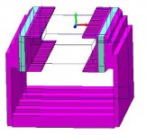
To make sure that the battlement of the polar pieces does not involve unevenness I did a simulation in 3d with the following drawing:
3d.JPG
The structure is a little different, as it has the magnets and polar pieces 30 mm high rather than 25 and also the dentition is exaggerated, but for the intended purpose it's okay. I limited the length to 100 mm because otherwise the calculation time would be excessive. Already so, the PC has taked 8 hours to make calculations, both for the numerous details of the structure and because in the area of interest I have set meshes not greater than 2 mm. The following chart is for a longitudinal line just below a top dents, basically on a side edge of the ribbon at a maximum 8 mm.
uniformità 3d.jpg
Exhausted the engine argument, in the next post I'll start the ribbons.
Attachments
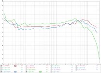
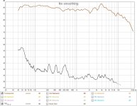
One thing I want to exhibit first: I made ribbons with Alu 10 um thick, 30um and 80 um, and apart from the rest, I noticed that by increasing the thickness of Al, the response to the highs fell before. Below is a comparison of ribbons in free air, mic at 2 cm, uncalibrated system
SPL spess.jpg
Red: 10 μm, blue: 30 μm, green: 80 μm
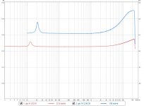
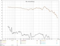
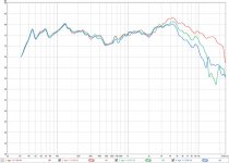
All the 80 um ribbons I made, with many variations, fell like that on the highs. Since theory states that weight affects performance but not frequency response, I have sought the reason for these results, and in the end I found what positively seems trivial: increasing the thickness of the Alu decreases the resistance in proportion, but the inductance remains practically the same. If for a 10 um thick ribbon the inductance is negligible compared to the resistance, it is no longer for an 80 um tape. Then I thought: I divide the 80 um tape into 4 strips and I rubbed it! No way! The R multiplies by 16, but the same is inductance. In the following chart you can see the impedances of a 10 um thick ribbon, without splitting into strips (red), and an 80 um ribbon divided into 4 strips (blue). The absolute values of resistances are not accurate, as with REW ground returns cause errors. Resistance measured in DC with the 4-wire method is 0.027 ohm for the 10 μm ribbon, and 0.073 ohm for the 80 μm ribbon, 4 strips in series.
impedance.jpg
SPL spess.jpg
Red: 10 μm, blue: 30 μm, green: 80 μm
All the 80 um ribbons I made, with many variations, fell like that on the highs. Since theory states that weight affects performance but not frequency response, I have sought the reason for these results, and in the end I found what positively seems trivial: increasing the thickness of the Alu decreases the resistance in proportion, but the inductance remains practically the same. If for a 10 um thick ribbon the inductance is negligible compared to the resistance, it is no longer for an 80 um tape. Then I thought: I divide the 80 um tape into 4 strips and I rubbed it! No way! The R multiplies by 16, but the same is inductance. In the following chart you can see the impedances of a 10 um thick ribbon, without splitting into strips (red), and an 80 um ribbon divided into 4 strips (blue). The absolute values of resistances are not accurate, as with REW ground returns cause errors. Resistance measured in DC with the 4-wire method is 0.027 ohm for the 10 μm ribbon, and 0.073 ohm for the 80 μm ribbon, 4 strips in series.
impedance.jpg
Attachments
Moving to the construction of the ribbons:
As I anticipated at the beginning, I used 12 g / m^2 impregnated paper to close the gaps at the sides of the ribbon. I tried celluloid impregnation (table tennis balls dissolved in acetone), and also silicone rubber for molding, shore 10.
In the end I preferred the second because with the first I get Fs a little higher. However, what determines the total compliance are predominantly the terminal suspensions.
For Alu, I use preferably adhesive tapes. Along the Alu on a glass, Alu up, cut to size (40mm x about 40cm), cut the slits forming the strips without cutting the ribbon liner, then roll it Alu down spreading it with water and soap, and when dry I remove the liner. At this point I used 2 processes:
--- In the first I attack on the entire ribbon a strip of paper about 6 cm larger than the ribbon, then cut the paper so that it leaves 2 cm per part for a length of 26 cm, +/-13 from the center. For the rest I cut the paper to the ribbon width. Then I corrugate or emboss it.
--- In the second I attack, centered, a depron strip 3 mm thick and 34 mm wide and 24 cm long (1 less than polar pieces), then attack 2 strips of paper 26 cm long to the remaining 3 mm left free on the sides, then 2 paper rectangles on the still free parts at the end of ribbon.
At this point I put it all on a woody shape with the smooth, vitrified surface and with a demoulding stuff, and soak the paper with a brush. When everything is dry I remove from the shape and make the end suspensions.
forma.JPG
With regard to these suspensions, my preference goes to a single U-bend made near the clamps, deep enough to have compliance. With 10 μm Alu it is enough an U 3 or 4 mm high, while with 80 μm Alu it must be at least 8 mm high. The U width I keeps it at about 5 mm. Below a photo of a ribbon to which I removed the side suspensions.
sosp term.JPG
The black part that you see is a silicone rubber sheet 100um thick glued to the open side of the U. This artifact allows the tape to make great moves without deforming. The gum is normally as wide as all the side suspensions and is also glued to them so as to continue the suspension until to the clamps. In this way the ribbon becomes almost airtight. Finally, I tinned the ribbon terminals, so that the electrical contact is reliable. This is very important when dealing with ribbons with resistances below 0.1 ohms.
Now mount the ribbon on the motor. In the lateral suspensions, the outer part, approximately 6mm, is used to attach the suspensions to the polar expansions. For this work I found a very convenient method:
---First I put the ribbon in the magnetic structure and fix it to the clamps, centered and with the right tension.
--- arrange the suspensions with the expected curvature.
--- pass a little brush soaked vith bostik very diluited over the part of the paper to be glued. The bostik impregnates the paper and passes it by sticking the paper to the polar pieces.
--- Before the bostik dry I adjust the position of the paper.
--- Wait 10' that dry
--- with the same brush I put the bostik on the wooden block and attack the wings of the silicone rubber film.
End. Now measurements in the free air.
Attachments
I did many measurements with the uncalibrated system. I have calibrated it later and I saw that in the uncalibrated measurements the SPL is about 25 dB less than the calibration made with the REW signal and the meter technics SH-8000. But time ago I had to change the electret capsule of the meter, of course with a non-original one, and it is my personal evaluation that the uncalibrated measurements are 20 dB below, and not 25. The powers (W input) are calculated net of drops on the connecting cable. The following results are among the best I've got:
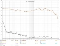
1) Ribbon with Alu 10 um smooth with 4 longitudinal cuts for 80% of the length. On Alu I glued only paper, side suspensions impregnated with celluloid, mic at 7 cm, 0.12W input, uncalibrated system
10um paper-30 dB.jpg
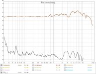
2) Alu 10 um tape without cuts, with depron, silicone impregnated side suspension paper, mic at 7 cm, 0.37W input, uncalibrated system. The depron weighs more than the paper (about 100g / m^2) and therefore the efficiency is lower, but also the THD is lower, at least at these levels.
10um depron-25 dB.jpg
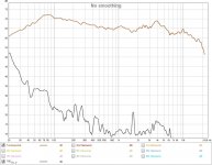
3)) ribb2: Alu 80 μm, 4 strips connected in series, with depron, silicone impregnated side suspension paper, mic at 3 cm, 0.43W input, uncalibrated system
80um depron-30 dB.jpg
At this point I have to anticipate that with the depron in the last measurements I had an unpleasant surprise, but I will talk later, since before I want to end the description of what I did.
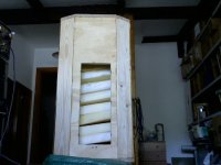
The box has nothing special: 40 liter internal, made of recovered wood, MDF 18 mm thick for side panels, above and below, 20 mm MDF for the back panel, 18 mm multilayer and pine wood respectively for the front panels and angled ones. All glued and secured with screws, except the back panel that is screwed only, no internal braces. The volume is filled with foam. I apologize for the realization, but I care about the aesthetic only in the final design.
cassa.JPG
box+speak.JPG
1) Ribbon with Alu 10 um smooth with 4 longitudinal cuts for 80% of the length. On Alu I glued only paper, side suspensions impregnated with celluloid, mic at 7 cm, 0.12W input, uncalibrated system
10um paper-30 dB.jpg
2) Alu 10 um tape without cuts, with depron, silicone impregnated side suspension paper, mic at 7 cm, 0.37W input, uncalibrated system. The depron weighs more than the paper (about 100g / m^2) and therefore the efficiency is lower, but also the THD is lower, at least at these levels.
10um depron-25 dB.jpg
3)) ribb2: Alu 80 μm, 4 strips connected in series, with depron, silicone impregnated side suspension paper, mic at 3 cm, 0.43W input, uncalibrated system
80um depron-30 dB.jpg
At this point I have to anticipate that with the depron in the last measurements I had an unpleasant surprise, but I will talk later, since before I want to end the description of what I did.
The box has nothing special: 40 liter internal, made of recovered wood, MDF 18 mm thick for side panels, above and below, 20 mm MDF for the back panel, 18 mm multilayer and pine wood respectively for the front panels and angled ones. All glued and secured with screws, except the back panel that is screwed only, no internal braces. The volume is filled with foam. I apologize for the realization, but I care about the aesthetic only in the final design.
cassa.JPG
box+speak.JPG
Attachments
I have put in the box only ribbons with Alu thick 80 um. With Alu 10 um I have not tried, given the results of the simulations.
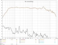
Ribb2 in box 40 l: Alu 80 μm, 4 strips in series, with depron, side suspension paper impregnated with silicone rubber, mic at 3 cm, 0.43W input, uncalibrated system.
ribb2 box-30dB.jpg
The position and heigth of the peak on the low has a good similarity, considering the uncertainties about parameter values, with the one provided by the SW "UniBox". Very good software.
At this point I put in front of the amplifier a modified notch filter for low correction and a order 1 filter for high correction. The result below:
ribb2 box-30dB_comp.jpg
Aside from some peaks on the THD that tell me I have to adjust something (however they are under 35dB), I will have to change the compensation on the highs with a second or third order. I'll do it later. For now I'm fine. Another ribbon made as ribb2:
Ribb3 = ribb2 except that I made cross engravings in the depron about each cm, in box 40 l and with electronic compensation, mic at 4 cm, 0.43W input, calibrated system
Attachments
Great thread, astonishing performance both frequency and distortion, thanks.Aside from some peaks on the THD that tell me I have to adjust something (however they are under 35dB)..
Not a much of a problem to have speaker artefacts at -35dB; that's wonderful.
B.
Now a look at the directivity.
Ribb3 in CB 40 l, mic at 20 cm, 0.43W input, with electronic compensation, calibrated system, red: 0 °, green: 30 °, blue: 45 ° smooting = 1/12
ribb3_angle.jpg
I had to do the measurement with a mic at 20 cm because at higher distances the responses are altering too much. I have walls and close objects, and putting even 8 cm thick absorbents does not work.
Curves begin to differentiate around 3000Hz, and at 10 KHz the 45 ° curve is about 8 dB below 0 °. I could calculate the dispersion by the width of the tape, but I wanted to do the same because I was hoping to improve it with an acoustic lens or a diffuser.
Instead, I only got a slight improvement with a lens made of soft foam polyurethane, but most attempts have come about unacceptable holes between 10 and 20 kHz. So I left the idea of the lens and I'm considering making the final ribbon less wide, 30 mm, even considering that I heard from this 100 cm^2 ribbon bass full, clean and robust, very satisfying. So even if the final ribbon will have 277 cm^2 rather than 370 will still be a good improvement over what's now already good.
I'm not a fan of omnidirecctionality, and I think a bit of directionality is right, but I would prefer that the curves begin to divide over 5 KHz
There is also the possibility of making the tape a little longer, eg 130 cm. I have to think about the problems involved
Attachments
Those speakers are wonderful. No reason to hear with your eyes by looking at curves.
1. There's nothing playing that is worth hearing over 10kHz (even if anybody could hear it... and almost nobody can really check their >10kHz hearing properly whatever they may falsely think).
2. 45-degrees is larger angle than covering your whole room!
3. 8 dB in the context of all the variation in room sound and human hearing is trivial perturbation.
Didn't we have some big arguments in this forum about beaming recently? An insignificant matter, in my opinion, and hardly worth bending speakers out of shape to combat beaming.
B.
Last edited:
Hi lupi,
Some other diyaudio member, I don't remember who nor in which thread, made some measurements on various thicknesses - and thus masses - of membranes and found a clear correlation between HF extension and thickness. Those that were thinner had (much) better hf extension. Made on electrostatic speakers so inductance may not matter here (?).
Cheers,
Jesper
P.S.: Given a fixed drive force I would also expect higher masses to cause a drop in HF response. Just consider moving 1 kg quickly back and forth with the same force as moving 1 gram. The 1 gram item will be moved much further.
All the 80 um ribbons I made, with many variations, fell like that on the highs. Since theory states that weight affects performance but not frequency response, I have sought the reason for these results,
Some other diyaudio member, I don't remember who nor in which thread, made some measurements on various thicknesses - and thus masses - of membranes and found a clear correlation between HF extension and thickness. Those that were thinner had (much) better hf extension. Made on electrostatic speakers so inductance may not matter here (?).
Cheers,
Jesper
P.S.: Given a fixed drive force I would also expect higher masses to cause a drop in HF response. Just consider moving 1 kg quickly back and forth with the same force as moving 1 gram. The 1 gram item will be moved much further.
Hi GentlevoiceHi lupi,
Some other diyaudio member, I don't remember who nor in which thread, made some measurements on various thicknesses - and thus masses - of membranes and found a clear correlation between HF extension and thickness. Those that were thinner had (much) better hf extension. Made on electrostatic speakers so inductance may not matter here (?).
Cheers,
Jesper
P.S.: Given a fixed drive force I would also expect higher masses to cause a drop in HF response. Just consider moving 1 kg quickly back and forth with the same force as moving 1 gram. The 1 gram item will be moved much further.
Perhaps in the case of electrostatic speakers it is as you say, but in the case of this ribbon it is certain that the fall on the highs is due to the inductance. In fact, if you look at the 80 um ribbon impedance curve in the previous page, and consider what is said in the context, that is, the curve is slightly shifted in up, at 10 KHz the impedance is twice as high as 1 kHz, so the inductance certainly causes a decrease of 6 dB at 10 kHz. As a further test I made a measurement by putting 1 ohm in series, and the curve was almost flat up to 20 KHz
Sorry, bat what is said in your P.S. applies to all frequencies, not just for those high ones. The theory is right.
Cheers
lupi
- Home
- Loudspeakers
- Planars & Exotics
- my ribbons full range in CB