My initial thought was that the voltage multiplier uses frequency in its multiplication so a lower mains frequency will result in a lower bias voltage resulting in the speakers not working. I looked at the PCB and there are spaces for additional components in the multiplier.
Pretty sure your PS board is close to the attached PS board (MLPS103) for later model SL3 (year 2000). Open holes are for larger ML models.
I've had T1 fail ($16 from ML) and heard about TRIAC1 failing.
But you say neither one works when plugged into 115VAC? I'm guessing someone plugged BOTH into 220VAC and then quickly sold them...?? Tell us more about their history!
I've had T1 fail ($16 from ML) and heard about TRIAC1 failing.
But you say neither one works when plugged into 115VAC? I'm guessing someone plugged BOTH into 220VAC and then quickly sold them...?? Tell us more about their history!
Attachments
Last edited:
The speakers are both mine.i bought them when I was living in the states. I moved to the uk and they have only ever been plugged into 115 transformed down from 230. All my other gear worked fine only the speakers failed to work. I contacted ml in the uk and they wanted £125 each to convert and I also had to ship them to London. Expensive and inconvienient so they are sidelined until I can find a better solution and what the problem is.
If you can pop the back off and take a picture of the power supply board we will know exactly which version of the board you have. If it is an MLPS102, 103, or 104 I can tell you how to bypass the 60hz frequency sensor "lock out" with one jumper soldered on the backside of the board. If desired, you can also switch to the 220V input configuration, but that would involve a few jumper and resistor changes. I'm not sure what your comfort level is with a soldering iron.
If you can pop the back off and take a picture of the power supply board we will know exactly which version of the board you have. If it is an MLPS102, 103, or 104 I can tell you how to bypass the 60hz frequency sensor "lock out" with one jumper soldered on the backside of the board. If desired, you can also switch to the 220V input configuration, but that would involve a few jumper and resistor changes. I'm not sure what your comfort level is with a soldering iron.
I took back off the board is mlps103 rev h. I am very handy with a soldering iron and would prefer to plug them directly into 230v so please advise.
Thanks for you help.
Excellent. 
Since you didn’t post a pic of your board, I grabbed a few available on line to help describe mods.
Hopefully the layout of your board is similar enough for you to easily understand what to do.
Mains Frequency Sense Bypass:
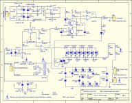
Refer to the schematic that Andersonix attached in post#5.
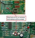
The 60Hz sensing circuit (IC1A/B) sends continuous trigger pulses to Q3. If 60Hz is used these pulses are of sufficient amplitude to turn on Q3 and keep C5 discharged so the ON/OFF threshold set at pin 10 of IC1C is overcome when music is sensed and will enable the HV supply. If 50Hz is used, the pulses are not of sufficient amplitude to turn on Q3, so C5 charges up thru R11 and as a results the threshold level at pin 10 cannot be overcome even if music is sensed. All you need to do is solder a jumper across the pins of C5 to bypass the frequency sensing function. Alternatively, you could remove C5 and replace with a jumper. This should have you up and running with the 230/115 step-down transformer setup.
110V to 220V conversion:
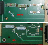
To switch transformer configurations from 110 to 220V, you need to do two things.
1) Remove Jumpers J1 and J3 (puts the primary windings in parallel), and solder in jumper J2(puts primary windings in series).
2) Remove the two 1.8K/3W resistors(R23, R24) and replace with two 7.5K/3W resistors. These series resistors provide the necessary voltage drop for the Zener string regulator shunted across the transformer secondary.
Let us know how it goes.
Since you didn’t post a pic of your board, I grabbed a few available on line to help describe mods.
Hopefully the layout of your board is similar enough for you to easily understand what to do.
Mains Frequency Sense Bypass:
Refer to the schematic that Andersonix attached in post#5.
The 60Hz sensing circuit (IC1A/B) sends continuous trigger pulses to Q3. If 60Hz is used these pulses are of sufficient amplitude to turn on Q3 and keep C5 discharged so the ON/OFF threshold set at pin 10 of IC1C is overcome when music is sensed and will enable the HV supply. If 50Hz is used, the pulses are not of sufficient amplitude to turn on Q3, so C5 charges up thru R11 and as a results the threshold level at pin 10 cannot be overcome even if music is sensed. All you need to do is solder a jumper across the pins of C5 to bypass the frequency sensing function. Alternatively, you could remove C5 and replace with a jumper. This should have you up and running with the 230/115 step-down transformer setup.
110V to 220V conversion:
To switch transformer configurations from 110 to 220V, you need to do two things.
1) Remove Jumpers J1 and J3 (puts the primary windings in parallel), and solder in jumper J2(puts primary windings in series).
2) Remove the two 1.8K/3W resistors(R23, R24) and replace with two 7.5K/3W resistors. These series resistors provide the necessary voltage drop for the Zener string regulator shunted across the transformer secondary.
Let us know how it goes.
Attachments
Thanks for sharing your successful outcome.
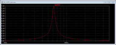
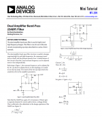
Based on PMs I have received, there seems to be a fair amount of interest in understanding the 60Hz discrimination circuit built around (IC1A/B). It is a little known bandpass circuit arrangement capable of high-Q responses with independent specification of frequency and Q using just a few passive parts. Attached is response of the Martin Logan 60Hz discrimination circuit along with an app. note on the DABP topology. I have also seen this circuit described as a Fliege type bandpass filter.
Based on PMs I have received, there seems to be a fair amount of interest in understanding the 60Hz discrimination circuit built around (IC1A/B). It is a little known bandpass circuit arrangement capable of high-Q responses with independent specification of frequency and Q using just a few passive parts. Attached is response of the Martin Logan 60Hz discrimination circuit along with an app. note on the DABP topology. I have also seen this circuit described as a Fliege type bandpass filter.
Attachments
- Status
- This old topic is closed. If you want to reopen this topic, contact a moderator using the "Report Post" button.
- Home
- Loudspeakers
- Planars & Exotics
- ML Aerius import from USA