Still playing with the rubber magnets, and i need some help! maybe others can shine a light on it. i cant seem to reach over 15 Khz and apparantly the SMGA did not either
https://youtu.be/yYtv1HMkFhU
I used a laminate of 12 mic poly 9 micron alu
i get the same results with 3 mic poly and 40mic alumnium tape. 3 mm wide. or wires 0.135 mm diameter. all responses look to fall of around 15Khz
even the smga (the one with wires) rolled of at 15khz. i am not sure if it really suppose to reach 20Khz as far as i remember it should
The weight of the conductor should have some influence to i guess. Bolsertst had some diagram somewhere with 3 6 12 micron and the rolloff. hope i can find it somewhere ") also im not sure if the same principals for esl aplly since a magneplanar works some what different
also im not sure if the same principals for esl aplly since a magneplanar works some what different
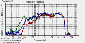
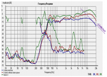
here i did a small test with weight
(RED) 10 micron aluminium foil (2.5mm wide)on 6 micron mylar measured @ menbrame side
(BLUE) 40 micron tape (3mm wide) on 3 micron Mylar. measured @ menbrame side
(GREEN) a laminate of 12 micron mylar with 9 micron aluminium etched (2.5 mm traces)
. they all come really close to each other to be honest
also im not sure if the same principals for esl aplly since a magneplanar works some what differenthere i did a small test with weight
(RED) 10 micron aluminium foil (2.5mm wide)on 6 micron mylar measured @ menbrame side
(BLUE) 40 micron tape (3mm wide) on 3 micron Mylar. measured @ menbrame side
(GREEN) a laminate of 12 micron mylar with 9 micron aluminium etched (2.5 mm traces)
. they all come really close to each other to be honest
Attachments
Would a denser "weave" of more conductors help? For older listeners (like myself) this taper is beyond audibility.
Does midrange response coverage of human voices, cellos, saxophones, etc. sound correct?
Would one of these mate well with your excellent Rubanoide?
Sent from my Nexus 6 using Tapatalk
Does midrange response coverage of human voices, cellos, saxophones, etc. sound correct?
Would one of these mate well with your excellent Rubanoide?
Sent from my Nexus 6 using Tapatalk
They sound ok to me, i doubt if i can hear beyond 15 kHz, maybe if i try hard with only a sine. but then still it wont do much in music for me. its just that i want to cover the whole spectrum it is more common to leave something away down low then in the highs, prob something to do with WAF factor and such or neighbors.
Denser weave, yeah i also think it might have something to do with the ratio of driven area vs undriven area. oen of the bass panels drop at 8 Khz while using same foil on the same mylar. only diference is the magnets are wider so therefore less traces on the foil compared to the tweeter/midrange....... hmmm that might be it. oh god do i need to cut my magnets even smaller well i at least try just going to cut them with a 3 mm mill instead of the 1mm mill the diference in size will be around 1 mm for each magnet.
i should be able to measure something then if it maters at all.
it is more common to leave something away down low then in the highs, prob something to do with WAF factor and such or neighbors.Denser weave, yeah i also think it might have something to do with the ratio of driven area vs undriven area. oen of the bass panels drop at 8 Khz while using same foil on the same mylar. only diference is the magnets are wider so therefore less traces on the foil compared to the tweeter/midrange....... hmmm that might be it. oh god do i need to cut my magnets even smaller
well i at least try just going to cut them with a 3 mm mill instead of the 1mm mill the diference in size will be around 1 mm for each magnet.i should be able to measure something then if it maters at all.
I'm offering a SWAG here (Scientific Wild *** Guess) that you have sufficient magnetic flux in the gap between rows of magnets, already.
Either more "turns" of wire or lighter traces (less massive foil) would increase the motive force/mass ratio.
Magneplanar in their earliest versions (which I have repaired) used fine gauge wire that was prone to corrosion failure.
What is the finest gauge foil you may procure, at reasonable cost?
Sent from my Nexus 6 using Tapatalk
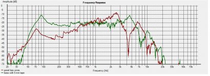
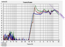
Heres a picture of 2 bass panels
1. RED is a bass panels with wires 8.5mm wide magnets and a gap of 1 mm
2. GREEN is a bass panel with aluminium foil 5 mm wide, 8.5mm wide magnets and a gap of 2 mm
so center to center
1 is 9.5 conductor to conductor
2 is 10.5 conductor to conductor , but the conductor is 4.5 mm wider.
the same 5 mm wide conductor on a panel with smaller magnet strips goes higher more in the range of 10khz
One more thing is the highs dont roll off but are a comb filter. so something happens in the foil is my guess. putting traces closer together makes the comb begin higher. at least this is what i see. i might nbeed to try some different material? or damp the **** of the mylar in between traces.
Attachments
Last edited:
yeah i did one panel with the wires magnepan uses although be it even thinner al wire. it reached as well 15Khz +- in the meaurement above i used 10micron thin al foil with no benefit. even changing that out for 40micron did not change much.
im a bit clueless.
i
im a bit clueless.
i
Last edited:
You know more than any 10 of us.
If you've already used fine wire, I suspect the membrane acts as a mass dampener.
Perhaps a magnetic bar could be applied as a "capo" to separate the HF section from larger excursions?
https://en.m.wikipedia.org/wiki/Capo
Sent from my Nexus 6 using Tapatalk
If you've already used fine wire, I suspect the membrane acts as a mass dampener.
Perhaps a magnetic bar could be applied as a "capo" to separate the HF section from larger excursions?
https://en.m.wikipedia.org/wiki/Capo
Sent from my Nexus 6 using Tapatalk
You know more than any 10 of us.
Well i realy really doubt that!!
i got some other ideas to, swap out the foil for some relaxing microwave foil
see what happens and maybe damp the mylar in between without Upping the resonance or it wont go as low, and last but not least maybe poke some holes in between the traces >? i will lose some ouput i guess but hell try it anyways.Aah a capo, never knew that was called a capo. well this would result in higher resonance. i could get the same result by tensioning them more. something i will try by tensioning them while playing some nice whitenoise and look at the spectrum to see what changes.
Thanks m8 for the input !
You only need to show 20kHz, no need to actuallly reach 20kHz, sorry, don't want to offend people
that would be cheating
i know it is silly since i dont hear it but i want it to be there 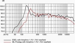
Hi,
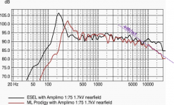
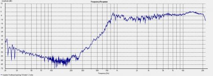
comparison ML panel with 12µm film and my panel with 3.5µm from 2006.
Mass related amplitude drop is clearly visible.
jauu
Calvin
THX CALVIN, probable has something to do with it but as you can see it drops pretty rapidly in my planars, so i guess there are 2 things playing a role at the same time. and one of them is keeping this mass loading in the shadows. since whatver i try i get this steep roll off even when lowering foil weight.
The steep roll-off is likely due to something in your measurement setup rather than diaphragm mass.
Roll-off due to mass is -6dB/oct as shown in Calvin's data. (attachment #1)
My comparison plots for different diaphragm mass were posted here:
http://www.diyaudio.com/forums/plan...tatic-speakers-microphones-5.html#post3427260
http://www.diyaudio.com/forums/planars-exotics/186840-david-lucas-esl-6.html#post3610816
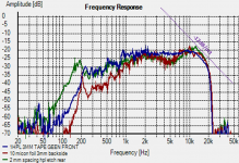
The roughly -12dB/oct slope looks to be the same in all your posted data.
Attachments #2 - #5 show your current ribbon data, and some ESL data you posted in another thread.
This slope is typical of microphone roll-off above the capsule resonance.
Q1: do you have calibration data for your microphone, and using it?
Q2: can you get access to and measure an XT tweeter?
They have flatish response out to 40kHz, so could be used to verify your measurement setup.
Roll-off due to mass is -6dB/oct as shown in Calvin's data. (attachment #1)
My comparison plots for different diaphragm mass were posted here:
http://www.diyaudio.com/forums/plan...tatic-speakers-microphones-5.html#post3427260
http://www.diyaudio.com/forums/planars-exotics/186840-david-lucas-esl-6.html#post3610816
The roughly -12dB/oct slope looks to be the same in all your posted data.
Attachments #2 - #5 show your current ribbon data, and some ESL data you posted in another thread.
This slope is typical of microphone roll-off above the capsule resonance.
Q1: do you have calibration data for your microphone, and using it?
Q2: can you get access to and measure an XT tweeter?
They have flatish response out to 40kHz, so could be used to verify your measurement setup.
Attachments
damn bolserst i kind of hoped you would chip in yeah about what you say it does remind me of the posts i made about the stacked ESL they had some weird rolloff as well, back then we thought it was the amounts of menbrames and weight.
about the mic, i got a UMIK with calibration file, and also got a home made uncalibrated panasonic based capsule. wich i think might be the same as in the umik. if i swapp them out they are almost the same. i do use the calibration file here it is as attachment.
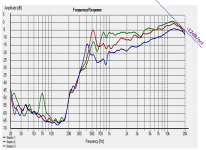
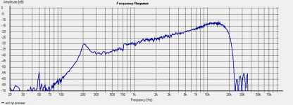
And here a clean measurement of a simple esl i used 2 different amps both match 100% if i change out to external soundcard or change laptop results are exactly the same.
If this mic is screwing me over that would be something.... i discarded sooo many designs based on this ****
the rise of the esl should extend further but decides to drop at ...... 15 khz.. 1 micron foil is used btw
yeah about what you say it does remind me of the posts i made about the stacked ESL they had some weird rolloff as well, back then we thought it was the amounts of menbrames and weight. about the mic, i got a UMIK with calibration file, and also got a home made uncalibrated panasonic based capsule. wich i think might be the same as in the umik. if i swapp them out they are almost the same. i do use the calibration file here it is as attachment.
And here a clean measurement of a simple esl i used 2 different amps both match 100% if i change out to external soundcard or change laptop results are exactly the same.
If this mic is screwing me over that would be something.... i discarded sooo many designs based on this ****
the rise of the esl should extend further but decides to drop at ...... 15 khz.. 1 micron foil is used btw
Attachments
- Status
- This old topic is closed. If you want to reopen this topic, contact a moderator using the "Report Post" button.
- Home
- Loudspeakers
- Planars & Exotics
- I cant reach above 15Khz on my planars