OOoh god damnnnnn !
i tried some of the ideas i had about the high freq problem ,for getting the biggest results i used the bass panels since they show the problem over a bigger bandwidth.
these are the measurements up close.
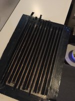
The panel in question:
A bass panel with wires attached like magnepan, magnet width 8.5mm 13 magnets used in total
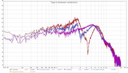
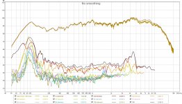
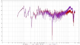
Picture one:
RED: Plain panel nothing hapened here, it has just wires and a some glue on the mylar to hold the wires.
BLUE:i added strips of gaffer tape to 8 out of the 13 magnets in between the wires really messy just a proof of concept. 62% coverage.
PURPLE: 100% coverage.
Picture 2 is the contraption
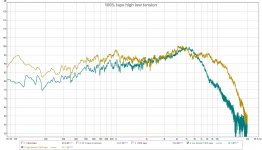
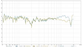
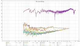
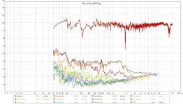
Picture 3 measurement of 100% coverage what does the tension do to the freq respionse?
Blue: neutral state
brown: bended state so i stretched the menbrame more then it is now.
That are some cool results if you ask me. still not sure if the same goes for the mid/high drivers but i can guess it does something to say the least.
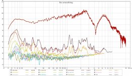
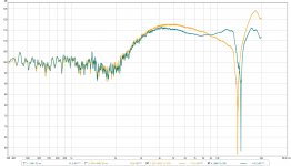
what else it does is lever out the bass to High frequency response and as well damp allot of crap in the distortion department picture 4 before any of these tests, picture 5 after tensioning and adding the tape. looks smoother,
One thing funny i just noticed , by adding tape i lost around 5 dB, but when stretching i gained 5 db again. so net not much lost")
i tried some of the ideas i had about the high freq problem ,for getting the biggest results i used the bass panels since they show the problem over a bigger bandwidth.
these are the measurements up close.
The panel in question:
A bass panel with wires attached like magnepan, magnet width 8.5mm 13 magnets used in total
Picture one:
RED: Plain panel nothing hapened here, it has just wires and a some glue on the mylar to hold the wires.
BLUE:i added strips of gaffer tape to 8 out of the 13 magnets in between the wires really messy just a proof of concept. 62% coverage.
PURPLE: 100% coverage.
Picture 2 is the contraption
Picture 3 measurement of 100% coverage what does the tension do to the freq respionse?
Blue: neutral state
brown: bended state so i stretched the menbrame more then it is now.
That are some cool results if you ask me. still not sure if the same goes for the mid/high drivers but i can guess it does something to say the least.
what else it does is lever out the bass to High frequency response and as well damp allot of crap in the distortion department picture 4 before any of these tests, picture 5 after tensioning and adding the tape. looks smoother,
One thing funny i just noticed , by adding tape i lost around 5 dB, but when stretching i gained 5 db again. so net not much lost
Attachments
Last edited:
One thing funny i just noticed , by adding tape i lost around 5 dB, but when stretching i gained 5 db again. so net not much lost
Hmm i forgot i might bended the magnets closer to the conductors as well so this might not be completely valid
Looks to me like the undriven space between wires may be moving in opposite direction than wires giving the sudden break just above 2 khz.
The purple trace I assume showing with full coverage of the damp tape??
Years ago I remember playing with this a bit. In the end when using larger wider magnets that result in large spaces between conductors I ended up simply making the foil traces full width from center of one magnet row to center of next magnet row. Same as Apogee bass panel. This seems like a waste of signal current in that quite a bit of current in conductor is now centered over the non ideal magnet flux region, BUT it ended up making a small difference in sensativity and a large difference in damping that area. I suspect the foil/adhesive/film combo being a much better impedance match than the tape ( I tryed all sorts of tapes and even thin felt) and seemed to damp much better
With these types of planers if going higher than bass duty it seems best to keep traces small and space between them small to avoid the issue. Problem is now we have very small magnets and a very small field wich means getting diaphragm very close to magnets to work well limiting excursion.
Anyway take above with some skepticism as I left that quest unfinished and its all speculation on my part.
Ha found my notes from years ago on this one. I looked at the magnet flux lines over top of the magnets and thought that a conductor in this area was useless. Then thought having the foil/adhesive over this area was simply damping that region better.
BUT then did some tests. simply holding a wire with DC current and scanning across the magnet array sure enough the wire is not moving perpendicular to diaphragm as we get closer to the center of a magnet. Its moving more at and angle as is to be expected when you look at the magnet field. HOWEVER even though the move is at an angle it is a force thats controlling the diaphragm and it is moving in a direction that works with the wires directly between magnets. This plus a bit of tension on diaphragm and the whole planer surface is being controlled and moving in right direction.
Sooo while there may be some damping of the foil/adhesive/film in effect by wide traces its much more the fact that it is being driven more than you might think.
BTW this was all done using magnets that were 15mm wide with a space of about 5 mm between.
Thx lowmass ! well my spacings are not that big magnets are 8.5 space between magnets only 1 - 2 mm Ill try some wide traces soon then first ill have to check if i am not measuring for nothing the past 3 years maybe you see somethign going wrong.
Here are some tests with the UMIK microphone from minidsp and a DPA 4061 omnidirectional mic. i used my digidesign mbox 2 soundcard as output for both tests and as input for the mic. i did run a loop and, it is as flat as a pancake so the problem is not there.
I must say i run this test on my main computer somehow my laptop wont allow the UMIK and the DIGIdesign soundcard at the same time. i will get a jack to jack tomorrow to see if the soundcard of the laptop itself in question is flat to.
Pic 1 is 30 cm away from a pair of genelec 1019 at tweeter height
Pic 2 very close like 1 cm or something at the tweeter.
i used the calibration file for the measurements with the umik of course !!!
One thing the Huge DIP at 14kHz i have no clue about, it could be anything the genelecs waveguide or something no clue. good thing they both have it so must be there for some reason
what i see is this , the UMik has a big fat peak at around 14 khz and then is almost 10 dB down to the DPA at 18Khz.
OOOOOH an yes i named the measurement 4060 but it is the low sens 4061 mic.
first ill have to check if i am not measuring for nothing the past 3 years maybe you see somethign going wrong.Here are some tests with the UMIK microphone from minidsp and a DPA 4061 omnidirectional mic. i used my digidesign mbox 2 soundcard as output for both tests and as input for the mic. i did run a loop and, it is as flat as a pancake so the problem is not there.
I must say i run this test on my main computer somehow my laptop wont allow the UMIK and the DIGIdesign soundcard at the same time. i will get a jack to jack tomorrow to see if the soundcard of the laptop itself in question is flat to.
Pic 1 is 30 cm away from a pair of genelec 1019 at tweeter height
Pic 2 very close like 1 cm or something at the tweeter.
i used the calibration file for the measurements with the umik of course !!!
One thing the Huge DIP at 14kHz i have no clue about, it could be anything the genelecs waveguide or something no clue. good thing they both have it so must be there for some reason
what i see is this , the UMik has a big fat peak at around 14 khz and then is almost 10 dB down to the DPA at 18Khz.
OOOOOH an yes i named the measurement 4060
but it is the low sens 4061 mic.Attachments
Last edited:
yes as Bolserst has pointed out the issue up around 15K is likley your measurment system.
I was talking about similar dips in response down around 2-3 khz.
I can tell you this much, my ears tell me theres a huge difference between narrow foil trace only between magnets and full coverage traces unless using panel below 500 hz or so. Much of my work at the time was a full range planer both flat and curved with foil/adhesive/film range from 4 micron each to about 20 micron foil/6 micron adhesive/12 micron film. Also did all designs in pleated similar to Apogee. A wide range and ALL were superior with full coverage traces.
I believe the Bolender planers are full coverage as well.
Bolnder are not if i remember correct , they use multiple traces trough. i must sort out my measuring system.... i am wasting my time playing with this crap if what i measure is not correct. all of my rubanoide adventures stacked esl AMTS etc all for nothing i am pretty pissed cailbrated my *** stupid minidsp. i want my 1000 hours back !!!!!!
i am on the brink of just say to some expensive company heeej yout got a mic thats calibrated >? (DPA b&K etc) telll me the price and recalibrate it and i buy it. since all the time i spend with this is useless if it does not say anything ! i might as well be the guy that says well it sounds nice so it is good. i dont want to be that guy
i am pretty pissed cailbrated my *** stupid minidsp. i want my 1000 hours back !!!!!!i am on the brink of just say to some expensive company heeej yout got a mic thats calibrated >? (DPA b&K etc) telll me the price and recalibrate it and i buy it. since all the time i spend with this is useless if it does not say anything ! i might as well be the guy that says well it sounds nice so it is good. i dont want to be that guy
Last edited:
well I wouldnt say all your past work is useless. There maybe an issue with measurment accuracy BUT not nessasarily measurment indication. Meaning that if there is a response upset the system may not be telling you exactly whats going on but its still telling you enough to know basically whats going on.
Most of the time we are trying to overcome a basic problem and just getting ballpark indication of it is enough to goto work on the issue. This is perhaps 90% of the work. from there if we want to refine things to some higher degree then of course we may need calibrated instruments.
The vast magority of your work is still useful info if interpreted well.
Yes. That would be a good HF reference for the top octave. If smoothly countersink mounted in the middle of a 1m diameter board, you can then measure directly on-axis and window out the edge reflection to ensure minimal ripples in the response... you mean like this tweeter from Vifa?
I posted calibration data for a group of 7 panasonic mic capsules a few years back... the mic, i got a UMIK with calibration file, and also got a home made uncalibrated panasonic based capsule. wich i think might be the same as in the umik. if i swapp them out they are almost the same. i do use the calibration file here it is as attachment.
http://www.diyaudio.com/forums/plan...request-amt-heil-diaphragm-4.html#post2586319
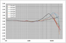
I took your data and overlayed it with my data in dashed black line.
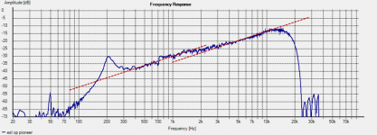
You can see that above the peak in the response, all my Panasonic capsules roll off sharply. The calibration data you received has the response flatten above the peak. I could be wrong, but I would guess that the true mic calibration data should follow something like the red dashed line I added above 10kHz.
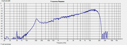
That is a fine measurement there, showing well the natural +6dB/slope of an unequalized ESL. Getting the same data from different sound cards helps answer the question of whether your soundcard and/or driver file are part of the roll-off problem. Looks like they are notAnd here a clean measurement of a simple esl i used 2 different amps both match 100% if i change out to external soundcard or change laptop results are exactly the same.
Attachments
Thanks for sharing your experience. I've often wondered about this aspect of planar magentics where there is often a significant portion of undriven diaphragm area that is just "along for the ride"....my ears tell me theres a huge difference between narrow foil trace only between magnets and full coverage traces unless using panel below 500 hz or so.
Hi bolserst thanks again for a the work you put in your replies !!! You've been a great help so many times where I/ and I guess others get stuck!
I looked at some responses of the cheap capsules to and noticed the same the curve you post are plots of the mic itself ? When used as call it will end up as mirrored? I mean positive values will be negative to compensate ? I looked at my cal and all numbers up high where the peak is are positive numbers. So according to you dashed red line 17 kHz should -5db so when used as call it will add 5 dB ?? Or am I doing it wrong ?
bolserst do you have a cal file if the red line I might be able to try?
Last question, if I just buy a crappy EMC 8000or slightly better could I let it be calibrated somewhere and have a bit more trusty measurements ?
Last edited:
Thanks for sharing your experience. I've often wondered about this aspect of planar magentics where there is often a significant portion of undriven diaphragm area that is just "along for the ride".
I think we all wondered about that
, my etched membranes have extra traces I called filler traces between traces there are useless traces to fill everything. I did this to most of my amt as well. I've seen it in commercial amt to like the one from Martin Logan.well I wouldnt say all your past work is useless. There maybe an issue with measurment accuracy BUT not nessasarily measurment indication. Meaning that if there is a response upset the system may not be telling you exactly whats going on but its still telling you enough to know basically whats going on.
Most of the time we are trying to overcome a basic problem and just getting ballpark indication of it is enough to goto work on the issue. This is perhaps 90% of the work. from there if we want to refine things to some higher degree then of course we may need calibrated instruments.
The vast magority of your work is still useful info if interpreted well.
Not useless that's true but for instance: I made some rubanoides and stopped working on it since it drops at 15 kHz thought it was hefty phase problems , I was busy with the stacked esl panels but stopped working on it since it dropped at 15 kHz to early and thought it was the weight or phase issues. Now the same for the planars. My goal every time was to create something that could play from midrange to high frequency 18-20 kHz as goal. The midrange and upper mid range was never a problem. But the amount of scrapped designs an tries to reach 20 kHz or smooth the huge hump are countless. I may have trown many random designs that should meausure rather good. So of course I learned allot of skills , materials and such and what certain things do ,but I never ended up after 3 years with a design I was feeling good enough about to finally build something with
not wasted time I enjoyed myself to and lost loads of money on materials and I still have allot materials so if I can get a mic I can trust I hapilly start all over !!!! And will redo every idea that was not a complete fail in other departments , so everything will be going faster
Last edited:
Thanks for sharing your experience. I've often wondered about this aspect of planar magentics where there is often a significant portion of undriven diaphragm area that is just "along for the ride".
yep, if you draw a picture of magnet flux lines and then draw lines perpendicular to these to represent the force on the conductor its easy to see that although the force lines out over the magnets are not perpendicular to diaphragm, they are in a direction that does useful work. The only area thats not is a small area right at the center of each magnet.
BTW some of my designs have been single trace foil, but most have been multi trace designs. I found no magor difference in perf. However resurch in other areas has shown that the multi trace configuration may have some advantage in mid frequency damping. This effect tunable by trace size/#/mass/ etc etc
Nice low mass !!! I will try some of the trace theory with soon, I am taking a 2 hour journey now to pickup a isemcon emx 7150. index
Should at least be better then a umik even without cal file , looking good. It does not fix all my design or anything but gives me at least a way better insight. I hope especially in the upper freq
Should at least be better then a umik even without cal file ,
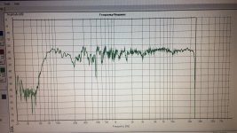
looking good. It does not fix all my design or anything but gives me at least a way better insight. I hope especially in the upper freq GOt the the new mic here a comparison
UMIK-1 vs Isemcon emx7150 both with cail file.
Pic 1 ferquency curve of a genelec 1019A at 30 cm
Pic 2 Distortion Umik-1
Pic 3 Distortion Isemcon emx7150
You can see the curve changed quit a bit smoother, which helps in terms of the 15Khz roll of i had. since with the umik it goes HIGH before it drops.
so you should level 15 Khz with the 15 Khz of the Isemcon emx7150, then the UMIK-1 would drop harder at 15 khz ... but another nice thing is if you look at distortion.
the Isemcon emx7150 is much more sensitive.
You can see clearly where the bass unit stops and the tweeter takes over in the same measurement, at around 2.1 Khz distortion from 0.099% skyrockets to 0.46% and so on. you can see the total noise floor increase, according to how much each unit is contributing to the total amount of output.
Distortion difference at 2.95khz
Isemcon emx7150 @ 2.95 Khz is 0.099% THD
uMIK-1 @ 2.95Khz 0.404% THD
I am looking forward to measuring the planars tomorrow. it might be nice it might be not but at least it is more honest i believe and i have more resolution.
the mic itself only differs around 1.66 dB at 10 hz . the rest from 20Hz - 20Khz differs max 0.8 dB. without calibration !
SAo im am impressed . there are also off mic calibration files and a file with measuring conditions like temperature etc , as well as ow much it differs at certain temperature differences .... way to much for me use but good it is there !
Letsssss Goooo
Attachments
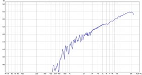
Here i measured the same ESL panel, (be it from a little further away.) with the new mic. looks slightly better.
Pic one old mic
Pic Two new mic
the 6dB per octave low roll of from 20khz and down is nicely visible. i did notice it is not exact 6 db more like 5. which cant be just fixes by a 6dB filter , i will end up short of high frequencies at 14 khz.
i used a crossover at 1.2 khz, and yeah its a different program somehow holm does not recognize my DAC input only output
Pic one old mic
Pic Two new mic
the 6dB per octave low roll of from 20khz and down is nicely visible. i did notice it is not exact 6 db more like 5. which cant be just fixes by a 6dB filter , i will end up short of high frequencies at 14 khz.
i used a crossover at 1.2 khz, and yeah its a different program
somehow holm does not recognize my DAC input only output Attachments
Last edited:
Yes, the plots represent the response of the mic itself when measuring an acoustic sound field that has perfectly flat amplitude vs frequency. Yes, the correction the software applies when using the calibration data is the mirror image of the response. I will see about modifying your existing calibration file to something like the red line…should have it early next week for you to try.… are plots of the mic itself ? When used as call it will end up as mirrored? I mean positive values will be negative to compensate ?...do you have a cal file if the red line I might be able to try?
I think you probably have already figured this out, but it all depends on the quality of the calibration performed. The EMC 8000 is reasonably stable with time as long as you don’t accidently leave it locked in a car in the hot sun. So, if you get good calibration data for it, you will have trustworth measurements.Last question, if I just buy a crappy EMC 8000or slightly better could I let it be calibrated somewhere and have a bit more trusty measurements ?
Can you post the calibration for your new mic? I would be interested to see how flat the response of the uncalibrated capsule is. Looks like it is providing a much flatter top octave measurement when calibrated than the UMIK.… im am impressed . there are also off mic calibration files and a file with measuring conditions like temperature etc , as well as ow much it differs at certain temperature differences ....
That looks a LOT better. -2.5dB down @ 20kHz vs -15dB.Here i measured the same ESL panel, (be it from a little further away.) with the new mic. looks slightly better.
If you look carefully, you will see that the slope is always 6dB, but there is a shift in the midrange due to the baffle effect of the spacer around the perimeter of the diaphragm. If you make your spacer wider or add an additional ring around it, you will notice the amplitude of the shift increase. If you somehow built an ESL with spacer width of only 1mm, there would be almost no shift noticeable. The frequency at which the shift occurs depends on the size of the panel; bigger panels have the shift at lower frequencies. The shift frequency also moves some when you start measuring very close to the panel.the 6dB per octave low roll of from 20khz and down is nicely visible. i did notice it is not exact 6 db more like 5. which cant be just fixes by a 6dB filter
When equalizing you use a 6dB slop filter + a very minor shelving filter to correct the shift.
Active Filters: 6 - Shelving highpass
Attachments
Last edited:
Yes, the plots represent the response of the mic itself when measuring an acoustic sound field that has perfectly flat amplitude vs frequency. Yes, the correction the software applies when using the calibration data is the mirror image of the response. I will see about modifying your existing calibration file to something like the red line…should have it early next week for you to try.
I think you probably have already figured this out, but it all depends on the quality of the calibration performed. The EMC 8000 is reasonably stable with time as long as you don’t accidently leave it locked in a car in the hot sun. So, if you get good calibration data for it, you will have trustworth measurements.
Can you post the calibration for your new mic? I would be interested to see how flat the response of the uncalibrated capsule is. Looks like it is providing a much flatter top octave measurement when calibrated than the UMIK.
That looks a LOT better. -2.5dB down @ 20kHz vs -15dB.
If you look carefully, you will see that the slope is always 6dB, but there is a shift in the midrange due to the baffle effect of the spacer around the perimeter of the diaphragm. If you make your spacer wider or add an additional ring around it, you will notice the amplitude of the shift increase. If you somehow built an ESL with spacer width of only 1mm, there would be almost no shift noticeable. The frequency at which the shift occurs depends on the size of the panel; bigger panels have the shift at lower frequencies. The shift frequency also moves some when you start measuring very close to the panel.
When equalizing you use a 6dB slop filter + a very minor shelving filter to correct the shift.
Active Filters: 6 - Shelving highpass
Nice ! You clarified allot again ! Good to know about filtering, , the panel in question had 15 mm wide spacer
I am in a train now but il post the cal file of the new mic when im home , uncalibrated the mic only drops 1 dB at 1 kHz Or so. I am really glad with the mic so far. IT opens up allot of possibilities of things i tried already without much succes. I can now redo. No problem since I like to fiddle around.
Bolserst don't spend any time on recreating the call I'll try to look up how to make one with the new mic and calibrate to that.but many thanks for offering to do it !!!!
- Status
- This old topic is closed. If you want to reopen this topic, contact a moderator using the "Report Post" button.
- Home
- Loudspeakers
- Planars & Exotics
- I cant reach above 15Khz on my planars