OK, this dipole tower has me thinking again, I was looking at the possibility of using one in place of my transmission line, just toying with the idea for now.
There are so many drivers available for an application like this, but the last time I studied specs on them has been over 12 years.
Do any high-performance-to-cost candidates ring a bell right off the bat?
I was looking at FEW's thread where he uses the Dayton RS225-8 inch bass/mids that measure quite well, I was hoping that they made a 6.5 in that line, but if there is one, I couldn't find it.
Like I said, just toying with the idea for now. Using the drivers that FEW did would set me back over 600usd for 6 per side, then again, cost isn't the main consideration..hmmm...
I'll probably just concentrate on the panels for now, but wanted to throw this out there as a running consideration.
Cheers
Last edited:
Oh, a 7..nice..Hi,
see the RS-180 lineup
jauu
Calvin
Shouldnt have narrowed the search down as much as I did..
Thanks Calvin
While I'm at it though ...what do you guys think? ..7 or 8?
Last edited:
OK, I re-read bengal's thread due to his panel size being similar, and think I have a definite plan, but want to run a few things by everyone.
Proposed panels would be 15x60 inches (380x1525mm), this should be plenty big area-wise, and loud with a 200-250Hz x-over. I thought about 150Hz but think I'll stay at 200-250 for several reasons.
Eleven wires per inch seems standard with the last few builds, I think I'll stick with that.
.0625" also seems good for spacing, check.
For segmentation, I'm thinking Configuration 2 for ease of construction.
Speaking of construction, I've lots of baltic birch, and think this should be strong and stable enough for frames/slats.
Would more in the way of step-up to get healthy SPL be advisable? (I'm assuming) ...as my current step-up is 75:1 IIRC.
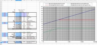
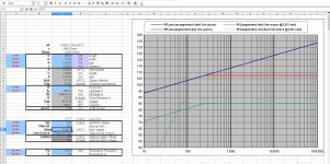
I ran some simulations, and this is what it spit out for 150, 200, and 250Hz/fL. (see attachments)
First set at 75:1 (150 & 250Hz/fL), second set at 150:1 (all 3). My bias supply output is 5.1k, so this is the number I punched into line ==>9, I hope that is correct.
Note: I did not delve into the full 'seg_esl_ui' program, I hope using what I did is OK, and the sims are correct, at least in the ballpark.
SPL increases significantly with the 150:1 ratio, I think me likey...")
The VTX Transformers seem a good choice for hybrid setups, but I am unsure of which to get, my current two per panel are these:
https://www.rapidonline.com/vigortr...sformer-230v-single-primary-50va-0-6v-88-5190
But I thought I saw where bengal ordered these(?):
https://www.rapidonline.com/vigortr...sformer-230v-single-primary-50va-0-9v-88-5191
Not entirely sure though...
However, I was reading golfnut's comments on transformers, and thought he said that the 50VA spec was on the large side. (could be wrong)
What's the alternative? ..lower VA with more transformers to achieve desired step-up? (total guess)
I tried following along with one of his posts describing choices, but as soon as the math/symbols start appearing, my eyes glaze over because I do not understand them.
Needless to say, I really need some guidance here.
Maybe a few recommendations with good performance/price ratio?
(I know I know, that's cheating using a shortcut..haha)
Anyway, overall, does the panel size, 150:1 step-up, 5.1k bias, 200-250Hz/fL, D/S etc. Jive with expectation of quality and quantity of sonics? ...seem at least feasible? Am I on the right track?
Enough for now, need to talk to my machinist friend and get going on a jig that will withstand the forces for a panel of this size.
Cheers
-Steve
Proposed panels would be 15x60 inches (380x1525mm), this should be plenty big area-wise, and loud with a 200-250Hz x-over. I thought about 150Hz but think I'll stay at 200-250 for several reasons.
Eleven wires per inch seems standard with the last few builds, I think I'll stick with that.
.0625" also seems good for spacing, check.
For segmentation, I'm thinking Configuration 2 for ease of construction.
Speaking of construction, I've lots of baltic birch, and think this should be strong and stable enough for frames/slats.
Would more in the way of step-up to get healthy SPL be advisable? (I'm assuming) ...as my current step-up is 75:1 IIRC.
I ran some simulations, and this is what it spit out for 150, 200, and 250Hz/fL. (see attachments)
First set at 75:1 (150 & 250Hz/fL), second set at 150:1 (all 3). My bias supply output is 5.1k, so this is the number I punched into line ==>9, I hope that is correct.
Note: I did not delve into the full 'seg_esl_ui' program, I hope using what I did is OK, and the sims are correct, at least in the ballpark.
SPL increases significantly with the 150:1 ratio, I think me likey...
The VTX Transformers seem a good choice for hybrid setups, but I am unsure of which to get, my current two per panel are these:
https://www.rapidonline.com/vigortr...sformer-230v-single-primary-50va-0-6v-88-5190
But I thought I saw where bengal ordered these(?):
https://www.rapidonline.com/vigortr...sformer-230v-single-primary-50va-0-9v-88-5191
Not entirely sure though...
However, I was reading golfnut's comments on transformers, and thought he said that the 50VA spec was on the large side. (could be wrong)
What's the alternative? ..lower VA with more transformers to achieve desired step-up? (total guess)
I tried following along with one of his posts describing choices, but as soon as the math/symbols start appearing, my eyes glaze over because I do not understand them.
Needless to say, I really need some guidance here.
Maybe a few recommendations with good performance/price ratio?
(I know I know, that's cheating using a shortcut..haha)
Anyway, overall, does the panel size, 150:1 step-up, 5.1k bias, 200-250Hz/fL, D/S etc. Jive with expectation of quality and quantity of sonics? ...seem at least feasible? Am I on the right track?
Enough for now, need to talk to my machinist friend and get going on a jig that will withstand the forces for a panel of this size.
Cheers
-Steve
Attachments


Last edited:
Hi wreckingball
Segmented speakers favour transformers with a lower winding capacitance and larger inductance than single segment ESLs, so smaller transformers are better.
Based on some measurements I did a while ago, on some 15VA transformers, you should be able to do well with four 230V/6V transformers.
The six volt rating at 50 Hz (60 Hz) will translate to 24V rating at 200 Hz (240Hz for 60Hz).
Each transformer will give you a 1:38 step up ratio. So put the four 230V windings in series, and the four 6 V windings in parallel to give a 1: 152 step up ratio.
The only catch is to make sure you DO NOT buy transformers with dual winding for 115V and 230 V.
Probably the most available transformer is one with two 6V windings - put the two in parallel. (so you will have eight 6V windings in parallel.)
regards
Rod
Thanks for the response, I follow the reasoning and the step-up calc makes sense now..
I picked these out of a couple different types, and they're listed as single 230V, are they correct? /Will work?
https://www.rapidonline.com/vigortr...ormer-230v-single-primary-15va-0-6v-0-88-5180
I hope so, this is a decent price =}
Speaking of which, there is a price break per part with a quantity of 10+..
Now, I saw in the other thread you specifying an even number for each panel, but bolserst posted a workaround that I didn't really look at too closely. (I'll look again)
The workaround was for three, IIRC, but could it work for five I wonder?
Would there be any harm running 5 or an even 6 per panel?
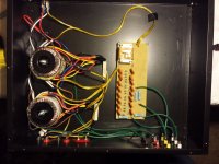
Also, the way I had my electronics situated for my curved panels was in a single box, both sets, two transformers per panel.
I stacked them vertically next to each other, bolted to the bottom plate of box, with thick isolation/shock mounts made of rubber/urethane, and the supplied big washers. (see attachment 1)
Can these toroidals be stacked on their side in a horizontal fashion? Or does that break an electronic rule I'm not aware of..?
And if they can't, do all 4 (or 5-6) need to be stacked? ..or could they be 2-high, next to each other? Follow?
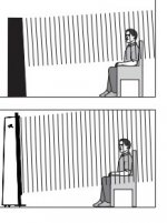
One last (trivial) question for anyone who knows: Does the radiation pattern of an ESL beam straight out, or is there comb filter effect due to the top/bottom of panel being further away from listener, as opposed to the center/ear-level section of the panel? Reason I ask is there's a guy claiming CFE on another forum, no biggie, just wondering... (see attachment 2)
Cheers
-Steve
I picked these out of a couple different types, and they're listed as single 230V, are they correct? /Will work?
https://www.rapidonline.com/vigortr...ormer-230v-single-primary-15va-0-6v-0-88-5180
I hope so, this is a decent price =}
Speaking of which, there is a price break per part with a quantity of 10+..
Now, I saw in the other thread you specifying an even number for each panel, but bolserst posted a workaround that I didn't really look at too closely. (I'll look again)
The workaround was for three, IIRC, but could it work for five I wonder?
Would there be any harm running 5 or an even 6 per panel?
Also, the way I had my electronics situated for my curved panels was in a single box, both sets, two transformers per panel.
I stacked them vertically next to each other, bolted to the bottom plate of box, with thick isolation/shock mounts made of rubber/urethane, and the supplied big washers. (see attachment 1)
Can these toroidals be stacked on their side in a horizontal fashion? Or does that break an electronic rule I'm not aware of..?
And if they can't, do all 4 (or 5-6) need to be stacked? ..or could they be 2-high, next to each other? Follow?
One last (trivial) question for anyone who knows: Does the radiation pattern of an ESL beam straight out, or is there comb filter effect due to the top/bottom of panel being further away from listener, as opposed to the center/ear-level section of the panel? Reason I ask is there's a guy claiming CFE on another forum, no biggie, just wondering...
(see attachment 2)Cheers
-Steve
Attachments
Last edited:
All sounds good except with D/S = 0.0625” you will want to use a lower bias…something around 3.5kV.OK, I re-read bengal's thread due to his panel size being similar, and think I have a definite plan, but want to run a few things by everyone.
Proposed panels would be 15x60 inches (380x1525mm), this should be plenty big area-wise, and loud with a 200-250Hz x-over. I thought about 150Hz but think I'll stay at 200-250 for several reasons.
Eleven wires per inch seems standard with the last few builds, I think I'll stick with that.
.0625" also seems good for spacing, check.
For segmentation, I'm thinking Configuration 2 for ease of construction.
Speaking of construction, I've lots of baltic birch, and think this should be strong and stable enough for frames/slats…. Anyway, overall, does the panel size, 150:1 step-up, 5.1k bias, 200-250Hz/fL, D/S etc. Jive with expectation of quality and quantity of sonics? ...seem at least feasible? Am I on the right track?
Transformer options:
Here are some links to the tests I performed on Bengel’s transformers:
http://www.diyaudio.com/forums/planars-exotics/286989-about-take-esl-plunge-29.html#post4752565
http://www.diyaudio.com/forums/planars-exotics/286989-about-take-esl-plunge-30.html#post4757159
An alternative for your project would be a set of transformers from an Acoustat Spectra 11. They have a step-up ratio of 140:1, work great with segmented panels, and can handle over 60Vrms @ 200Hz. They show up from time to time on ebay…actually, I have a pair I will be listing sometime in the near future. If interested, send me a PM.
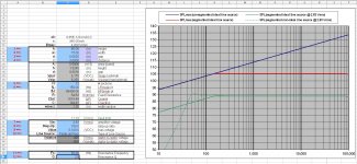
With fL=200Hz and bias = 3.5kV, a step-up ratio of 150:1 will play louder than 75:1 for a given volume setting, but the maximum peak SPL before you start generating ozone will be the same. The difference will be that you will reach that level at a lower volume setting with the 150:1 than with the 75:1. Basically no matter what combination of bias, step-up ratio, and input voltage you try, you won’t be able to exceed the red curve on the plot without starting to generate ozone. Oh, speaking of the red line, meant to ask if you meant to set the distance to 3m because that is your listening distance? Otherwise, you might set it to 1m so SPL will line up more with sensitivity specs for dynamic drivers.
The spreadsheet has an estimated limit for the amplifier output at which ozone would start to be generated in cell “C30”. When you exceed the limit, the Vin: input cell will be highlighted in red. For the 150:1 you would reach that limit at roughly 27Vrms, pretty close to the typical output of a 100W/8ohm amplifier. For the 75:1 you wouldn’t reach the limit until twice that, or 54Vrm…typical of output from a 350W/8ohm amplifier.
Due to the dynamic nature of music, you can generally use a larger amp than these numbers indicate without generating much ozone. However if you play steady test tones, you will find the limitation a good estimate of when air starts breaking down and ozone generated.
Well, I just got an e-mail from Interstate Wire, they checked with 3 different suppliers, and cannot obtain the wire I was after...
Here: WIA-2001-0 - UL AWM Style 1429 | Interstate Wire
This is the wire that Charlie recommended, also I believe the same that bengal used.
Does anyone have another type of wire to recommend? ..when I google the type Calvin posted, I mostly get sites from across the pond, no idea there..
What is it about this specific wire? I seem to remember something about the PVC being cross-linked, IDK?
I'm not sure, I'm afraid..hmmm..
Help?
...Does the radiation pattern of an ESL beam straight out, or is there comb filter effect due to the top/bottom of panel being further away from listener, as opposed to the center/ear-level section of the panel? Reason I ask is there's a guy claiming CFE on another forum, no biggie, just wondering...
The “multiple arrival time” from line sources(even infinitely long) is visible in the native impulse response as an exponential decay after the first arrival peak.
Bascially, sound from the portion of the line directly in front of you arrives first, then as you work above and below that location, the sound arrives later and reduced in amplitude.
However, once you EQ the line source to correct for the tilted response(with segmentation or other means), you will find the EQ has fixed the impulse response as well. Imagine that, frequency and time domain are directly related for minimum phase transducer
So in the end, it is a non-issue...although people like to keep saying it is.
Let me know if it doesn’t make sense. Here are some links to discussion on the topic.
http://www.diyaudio.com/forums/mult...rical-cylindrical-plane-wave.html#post4519720
http://www.diyaudio.com/forums/mult...cal-cylindrical-plane-wave-2.html#post4522843
Last edited:
All sounds good except with D/S = 0.0625” you will want to use a lower bias…something around 3.5kV.
Transformer options:
Here are some links to the tests I performed on Bengel’s transformers:
http://www.diyaudio.com/forums/planars-exotics/286989-about-take-esl-plunge-29.html#post4752565
http://www.diyaudio.com/forums/planars-exotics/286989-about-take-esl-plunge-30.html#post4757159
An alternative for your project would be a set of transformers from an Acoustat Spectra 11. They have a step-up ratio of 140:1, work great with segmented panels, and can handle over 60Vrms @ 200Hz. They show up from time to time on ebay…actually, I have a pair I will be listing sometime in the near future. If interested, send me a PM.
With fL=200Hz and bias = 3.5kV, a step-up ratio of 150:1 will play louder than 75:1 for a given volume setting, but the maximum peak SPL before you start generating ozone will be the same. The difference will be that you will reach that level at a lower volume setting with the 150:1 than with the 75:1. Basically no matter what combination of bias, step-up ratio, and input voltage you try, you won’t be able to exceed the red curve on the plot without starting to generate ozone. Oh, speaking of the red line, meant to ask if you meant to set the distance to 3m because that is your listening distance? Otherwise, you might set it to 1m so SPL will line up more with sensitivity specs for dynamic drivers.
The spreadsheet has an estimated limit for the amplifier output at which ozone would start to be generated in cell “C30”. When you exceed the limit, the Vin: input cell will be highlighted in red. For the 150:1 you would reach that limit at roughly 27Vrms, pretty close to the typical output of a 100W/8ohm amplifier. For the 75:1 you wouldn’t reach the limit until twice that, or 54Vrm…typical of output from a 350W/8ohm amplifier.
Due to the dynamic nature of music, you can generally use a larger amp than these numbers indicate without generating much ozone. However if you play steady test tones, you will find the limitation a good estimate of when air starts breaking down and ozone generated.
*edit* Those transformers you tested and linked above, which ones were they? Model #?
Great info, thanks much.
Yea, I suspected as much as far as the SPL/red-line, and the bias, but wasn't sure.
So the spacing has to be increased, or the bias decreased...
Which is preferable? Any difference in sonics? Pros and cons?
When I built my bias, I placed two taps at 3.8k, I suppose I could just use those and be careful with the volume, eh?
My amp is an Emotiva XPA-5, which is rated for 200w @8 ohms, and 350w @4ohms 20-20 all channels driven.. Might be overkill to have step-up overly high..hmmm...
Is it a relief on the amp to run the ESL electronics over-sized, or doesn't it matter much?
I'll pay more attention to cell C-30 and play around with it some more, good info/explaination, thanks again.
The 3 meters is right around my listening distance, that's why that's there, I'll play around with that to see comparable dynamic driver SPL.
That's a lot of questions, I'll stop now...
I'll shoot you a PM before I order/change my step-up.
*edit 2* Oh, and more great info (and news), in post #31.. ;^ }
Cheers
Last edited:
Thanks for the response, I follow the reasoning and the step-up calc makes sense now..
I picked these out of a couple different types, and they're listed as single 230V, are they correct? /Will work?
https://www.rapidonline.com/vigortr...ormer-230v-single-primary-15va-0-6v-0-88-5180
I hope so, this is a decent price =}
Speaking of which, there is a price break per part with a quantity of 10+..
Now, I saw in the other thread you specifying an even number for each panel, but bolserst posted a workaround that I didn't really look at too closely. (I'll look again)
The workaround was for three, IIRC, but could it work for five I wonder?
Would there be any harm running 5 or an even 6 per panel?
Also, the way I had my electronics situated for my curved panels was in a single box, both sets, two transformers per panel.
I stacked them vertically next to each other, bolted to the bottom plate of box, with thick isolation/shock mounts made of rubber/urethane, and the supplied big washers. (see attachment 1)
Can these toroidals be stacked on their side in a horizontal fashion? Or does that break an electronic rule I'm not aware of..?
And if they can't, do all 4 (or 5-6) need to be stacked? ..or could they be 2-high, next to each other? Follow?
One last (trivial) question for anyone who knows: Does the radiation pattern of an ESL beam straight out, or is there comb filter effect due to the top/bottom of panel being further away from listener, as opposed to the center/ear-level section of the panel? Reason I ask is there's a guy claiming CFE on another forum, no biggie, just wondering...
Cheers
-Steve
Yes those transformers are what I had in mind (different brand only).
See Bolserst's links for wiring up the transformers. If you can get step up ratio near 150, and good input voltage rating, there is no need for additional transformers, but if price break is favourable, you will have a couple of spares. Adjusting the step-up ratio to match the maximum amplifier OP voltage, as bolserst suggests, is a good idea.
The insulation on mains transformers is supposed to be good for 4 kV breakdown (DC for some minutes), but an extra layer of insulation would not hurt. I've used PTFE baking sheet - but any plastic should do. They can be stacked pretty much any way you want then.
Re comb filter effect. In the horizontal direction, the segmentation solves the problem completely, so long as the segments are less than 1 wavelength wide ( say < 17 mm at 20 kHz), but slightly smaller is a bit better.
In the vertical direction, the ideal is for the ESL to occupy the full floor to ceiling space so that the reflections from the floor and ceiling make it behave as though it is infinitely tall - again no comb filter effect. For ESLs that do not occupy the whole floor to ceiling space it gets very complicated, but the simple story is that the ESL produces a cylindrical wavefront without comb effects for most of the frequency range, and at low frequencies you do start to get some departures from ideal - but no frequencies with zeros as for the true comb filter.
Regards
Rod
Thanks, just the answers I was looking for...
If I end up liking these panels and this setup enough, I just may build a floor to ceiling pair for the main-floor home-theater, as there are no obstructions on either floor or ceiling in the living room.
Time will tell, but it doesn't hurt that there is no WAF to contend with..
In case I do build, I'm assuming the above mentioned transformers would not work, and that I'd need something completely different with certain leakage inductance and capacitance etc.? Is that correct? (seem to remember 9v secondary)
Also, since I think wire for a floor-to-ceiling pair would be difficult to work with at those lengths, anyone hear of a known source of PCB large enough here stateside?
Speaking of which, an off-the-wall question: Anyone know if using thick aluminum foil on a sufficiently insulative substrate would work for stator material?
I'm assuming not, but I'm sure I'm not the only one that's ever thought of this ...probably would have been widely used by now if it was feasible. (just thinking/typing out loud again..haha..)
Anyway, this floor-to-ceiling would be for another time, (months out) but I thought I'd ask questions about the transformers etc. while we were on the subject.
Cheers
-Steve
Last edited:
If you want to use the type/size wire that Charlie used, you are looking for Type-B PVC wire (also known as MIL-W-16878 wire).Well, I just got an e-mail from Interstate Wire, they checked with 3 different suppliers, and cannot obtain the wire I was after...
The size is 20gauge solid wire with 0.01” thick PVC insulation.
I have purchased directly from Jaguar wire before. You might give them a call and see if they have it in stock.
Their product code is JB2001: Type-B PVC Insulated Wire - Jaguar Industries
VTX-146-015-106: https://www.rapidonline.com/vigortr...ormer-230v-single-primary-15va-0-6v-0-88-5180*edit* Those transformers you tested and linked above, which ones were they? Model #?
You will find that for a given fL, the red line won’t change level with change in spacing; only the bias and stator voltages required to reach the red line will change. The only way to move the red line is by changing fL or total width. In general, it is best to use as small a spacing as possible so lower voltages can be used. You just need to make sure the spacing is large enough to reach the SPLs you want without the diaphragm hitting the stators. For hybrids crossing in the 200Hz range, 1/16” is a good compromise.Yea, I suspected as much as far as the SPL/red-line, and the bias, but wasn't sure.
So the spacing has to be increased, or the bias decreased... Which is preferable?
It won’t really matter as long as you aren’t running into saturation. Using a slightly over-sized transformer for the task will ensure that isn’t a problem.Is it a relief on the amp to run the ESL electronics over-sized, or doesn't it matter much?
Excellent. Thanks again for the info in this preliminary stage of the project, this sums things up nicely..
I will be contacting J-wire tomorrow.
I'm sure there'll be other concerns/questions as i move along and make progress, but we'll burn that bridge when due, your post is a big help...
*****************************************************
Well, my curiosity has got the better of me again, so I'm just going to throw this out there since it's my thread..
I looked at DIY-ing PCB for a possible future build, but it seems like a money/time drain.
I did, however, find the below product ...seem workable (?)
Keep in mind, I overlook the obvious sometimes....HA!
On the surface, this looks like a candidate for stator material if CNC'd, but what does anyone else think?
Interested in opinions:
https://www.alibaba.com/product-detail/PCB-CCL-base-material-fr4-Copper_60603920004.html
Cheers
-Steve
I will be contacting J-wire tomorrow.
I'm sure there'll be other concerns/questions as i move along and make progress, but we'll burn that bridge when due, your post is a big help...
*****************************************************
Well, my curiosity has got the better of me again, so I'm just going to throw this out there since it's my thread..
I looked at DIY-ing PCB for a possible future build, but it seems like a money/time drain.
I did, however, find the below product ...seem workable (?)
Keep in mind, I overlook the obvious sometimes..
..HA!On the surface, this looks like a candidate for stator material if CNC'd, but what does anyone else think?
Interested in opinions:
https://www.alibaba.com/product-detail/PCB-CCL-base-material-fr4-Copper_60603920004.html
Cheers
-Steve
PCB stators are definitely a viable option for large segmented ESLs.
If you've got access to a CNC machine with adequate precision, PCB stators may not cost any more than PVC wire stators.
In case you had missed it, there was a build thread with CNC PCB stators.
A few links from the thread with pics:
- First attempt at CNC segmented PCB stator: first-time-esl-builder-Post#54
- Final CNC results: first-time-esl-builder-Post#138
- Stators coated and ladder resistors installed: first-time-esl-builder-Post#159
Thanks for reminding me of james' thread, I had forgotten about that.
Tried in vain to get a quote for wire by the weekend, no dice.
I figure I need around 3700 feet (some spare) for this build, what does that amount of wire cost going on past experience? (rough estimate is fine)
Anyway, I was kind of thinking out loud that going the PCB/CNC route could actually be cheaper than going the wire route, but after re-reading that thread, with all of the complications including coatings etc. Cutting bits dulling, special diamond bit to clear back the copper I'm not so sure I want to go that direction.
Let me back up:
I was weighing option costs and thought, with an order of 5 sheets (minimum) of panels (1020x1220mm) PCB from my link, that $25 ea. was a decent price.
By my estimate, I could get 15 ~ 49x13.3" *or* 40x16.2" stators for $125. Pretty good if you ask me. *edit* there are 3 sizes, largest of them would permit 49x14.2" or 43x16.2".
Of course I'd have shipping cost, CNC costs, cutting bits to provide/replace (see below), and coating cost tacked on to that, but still may be cheaper than wire.
Thoughts?
BTW, I posted the wrong link upthread, the correct one is for single side CCL PCB here: https://www.alibaba.com/product-det...60576231800.html?spm=a2700.8239084.0.0.HuuBBz
There's two things I'm not sure of, and that's, 1) the thickness of the copper foil, and 2) the thickness of the whole PCB panel. I'm assuming there are choices to be specified, I need to send some questions their way.
My machinist friend has access to a CNC machines on a 24/7 basis, now I'm sure he'd want some compensation for his time, plus replacing /buying bits, but I'm just trying to weigh all of this out.
Would love to hear people's thoughts/opinions on all this..
Cheers
Last edited:
CNC I had hoped to use does not have long enough capability for a panel this size, too bad, I was hoping for ease of assembly that PCB would have afforded.
Plus with the tolerances needed for milling and not etching the Cu back from the holes would have been a concern. Devils in the details, arrggh..
Unless something changes, I'm back to wire.
I seem to remember that although Charlie was successful with his stretching jig, there was a misalignment problem involving friction/possible buckling (??)
I'd like to avoid any potential problems, but I can't find the post/thread where correction for this was stated/described...hmm..
Still killing me that I don't know what I'm in for price-wise on 3700ft. of wire.
Patience may be a virtue, but I guess I got shorted in that department.
Unless something changes, I'm back to wire.
I seem to remember that although Charlie was successful with his stretching jig, there was a misalignment problem involving friction/possible buckling (??)
All of the concerns expressed by myself and others about my stretching jig turned out to be non-issues in the finalized design that I actually built and used.
Believe it or not, I spent far more time designing the wire stretching jig than I spent on the panel design itself.
A unique feature of my jig is that the stator's wooden support lattice is assembled and glued down over the wires, in the stretching jig --- as opposed to stretching wires over a pre-assembled support lattice. The advantage of this approach is that the wires and support lattice are assembled against a perfectly flat jig platform; which results in the finished stator being perfectly flat and the glue lines that bond the wires to the lattice are perfectly flush to the surface of the wires rather than standing proud.
I highly recommend this jig design and I will gladly provide a CAD drawing to anyone who wants it.
Last edited:
- Status
- This old topic is closed. If you want to reopen this topic, contact a moderator using the "Report Post" button.
- Home
- Loudspeakers
- Planars & Exotics
- The Thrill is Gone.. S-ESL Build