Thanks for the generous comments, CharlieM. Since they come from a man who has made such nice ESLs I'm most appreciative.
Clearly there are differences of opinion on how best to make the measurements. Not surprising, given the fact there's no perfect method. Thanks for making your software freely available CharlieLaub. I've not worked with it yet (I'm about to download it) but it clearly is the result of a lot of work.
Wesayso: I agree the video was "a trip." I haven't seen evidence in my speakers of resonances with such high Qs that they'll ring for dozens of cycles so I agree the poster's concerns may be a bit overblown.
Few
Thanks for the generous comments, CharlieM. Since they come from a man who has made such nice ESLs I'm most appreciative.
Clearly there are differences of opinion on how best to make the measurements. Not surprising, given the fact there's no perfect method. Thanks for making your software freely available CharlieLaub. I've not worked with it yet (I'm about to download it) but it clearly is the result of a lot of work.
Wesayso: I agree the video was "a trip." I haven't seen evidence in my speakers of resonances with such high Qs that they'll ring for dozens of cycles so I agree the poster's concerns may be a bit overblown.
Few
You do have an inspired design Few.
Oh so many boxes with drivers in them. They work, but they lack a flair or statement quality. Your line is imposing and it has become more a piece of sculpture than a monolithic box. Making an imposing structure a little easier to deal with in the real world of a home.
Hats off to you sir. I like it.
As for measurements.
CharlieLaub has given you one of the best methods to make a measurement of a dipole. Short of outside polar measurements that should present you with a type of dual balloon squashed polar measurement.
If you want to travel down the room correction road Rephase is a pretty awesome program for room correction. And I think the latest version of REW is capable of generating the files for working within Rephase.
Thanks Mark. I very much appreciate the compliment. I have to admit to spending quite a bit of time on the design and construction in the hope of achieving a refined result so I'm pleased you and others have found it attractive. Now I need to back it all up with decent crossover and equalization design!
I will certainly try the nearfield approach again. As I said in a previous post, I tried a quick and dirty approach early on but haven't gone back with the tools to actually get the job done. I'm guessing I will find some deviations from the predictions as a result of the array of six woofers per side, as predicted by wesayso, but it will likely be instructive to have that "nearfield plus delayed and inverted" result as a reference point. I think I'll likely try using Matlab to do the calculation since it's a package I'm already comfortable with.
By the way, I found that I'm not the first person to think about modifying the impulse response to extract useful results at lower frequency. No surprise there! None other than John Kreskovsky posted back in 2007 some of his thoughts on the subject: "Recovery of Low Frequency response by Impulse Editing..."
Few
Treat your woofers as a unit. Basically a tall pulsing column. They behave as one as the wavelength of sound you are using them up to is longer than your column height. 64 hertz wavelength is approximately 16 feet, 128 hertz approximately 8 feet. As you go higher in frequency the woofers end up being individual points in space reproducing their contribution. But that is quite a way up into the midrange.
As long as all the drivers are wired in the same polarity they will behave as a single unit. That is why Charlies advice is a very good way to approach the measurement.
John is definitely one of the sharper tools in the shed. I look at what he presents to.
You won't go wrong following that method either.
What is paramount is that each method will produce slightly different results. And that is perfectly normal. I have no end of fun getting measurement son same product runs of driver made for me. Measurements in China done by competent people are not always easy to reproduce. Even when I know the equipment, have calibrated the equipment and have used it myself.
There are always different factors like temperature and humidity as well as reflective surfaces when you are trying to measure the low end performance of a loudspeaker array.
Working through another measurement session. It's nice to have the Christmas tree out of the way!
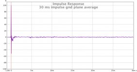
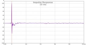
I worked a bit more with ground plane measurements, and now that I know how to average measurements I've gotten cleaner looking impulse response measurements. These are for one planar magnetic tower (no woofer contribution), no equalization or windowing, just a LR 60 Hz high pass to protect the speakers (which will be crossed over around 150 Hz or so to the woofers). The tower speaker was tilted toward the floor by 7 degrees.
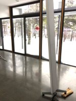
I'm including both a 30 ms time span and 10 ms one as well so the early details are more clear. I'm surprised how little the room intrudes into these averaged results considering it's not what you would call anechoic! In the photo the mic is lying on the acoustically reflective polished concrete floor at the left, the wall of acoustically reflective windows reveals the local weather beyond, and part of the tilted planar magnetic tower is visible in the foreground.
All this raises the question of whether these nicer-to-look-at impulse responses have any relevance to the way I should equalize and crossover the speakers, or to the way they'll sound if I don't lie with my ear against the floor.
In any case, I'm going to make my first attempt to adding rePhase to the mix once I take a few more measurements.
Few
I worked a bit more with ground plane measurements, and now that I know how to average measurements I've gotten cleaner looking impulse response measurements. These are for one planar magnetic tower (no woofer contribution), no equalization or windowing, just a LR 60 Hz high pass to protect the speakers (which will be crossed over around 150 Hz or so to the woofers). The tower speaker was tilted toward the floor by 7 degrees.
I'm including both a 30 ms time span and 10 ms one as well so the early details are more clear. I'm surprised how little the room intrudes into these averaged results considering it's not what you would call anechoic! In the photo the mic is lying on the acoustically reflective polished concrete floor at the left, the wall of acoustically reflective windows reveals the local weather beyond, and part of the tilted planar magnetic tower is visible in the foreground.
All this raises the question of whether these nicer-to-look-at impulse responses have any relevance to the way I should equalize and crossover the speakers, or to the way they'll sound if I don't lie with my ear against the floor.
In any case, I'm going to make my first attempt to adding rePhase to the mix once I take a few more measurements.
Few
Attachments
Nice.
Now that you have that battle won and in the bank, how about some on and off axis. Your nearfield measurements are nice.
The off axis are the ones that can tell you quite a bit about the sound.
Vertical polars would be interesting. But as most peoples ear height is around 37 to 39 inches from the floor that height from the floor is of most interest.
I agree directivity is one of the next questions. I haven't yet explored whether my two-trace conductor pattern will actually do anything useful in that regard so that's a big looming question. I need to try just driving the central "tweeter" section of the diaphragms and see if there's broader directivity in the high frequencies. (I'm not sure that's the right way to use the word directivity but I don't like "dispersion" in this context because that already has a very clear and very different meaning when it comes to wave propagation.)
By the way, I found that if I put the mic where the wall of windows meets the concrete floor I can get clean impulse tails with fewer measurements averaged. Just 3 or 4 measurements with the mic moved a few inches between measurements yields quite clean results for 30 ms or more. Now I need to clean up the response in the first millisecond. I know that a couple planar diaphragms had their tension disrupted during the mounting process. I can hear a buzz now and then when making frequency response measurements and I'm guessing it's from a loose diaphragm. I really don't like the way I mounted things but I was eager to get things together so I could see if any of this was going to work! I should do some refining now that I know the speakers will make music.
A few questions have arisen through this process, two hardware/software questions and one that's about where the theory's rubber hits the road. I welcome any insights.
1) When running Room Eq Wizard on a MacBook Pro I find a surprisingly large fraction of the frequency sweeps yield faulty results. Often the extreme high frequencies are missing in action, and that seems to correlate with a lot of pre-ringing on the impulse. Have others seen this, and perhaps discovered a cause (and hopefully a cure)?
2) Again running the software on the MacBook, when I try to import the REW filter settings into the miniDSP plug-in I'm using (miniSHARC 4x8) the import fails. I can see that REW is generating a text file with the filter settings but when I click "import" the plug-in the screen flashes briefly but there's no sign of the filter settings being imported. Am I just doing something stupid? I was trying this with the PEQ portion of the plug-in, not FIR filters, by the way.
3) I discovered I don't fully understand tall line arrays. An infinitely tall tower would have to show no variation in response along its height since all heights would, in effect, be identical. So it's the tall but finite height of the tower that leads to the lobing along the vertical axis. That's the starting point of my incomplete understanding. On to what I'm seeing with my measurements. To what extent do towers over 8 feet tall, on a highly reflective floor, behave as if they were infinitely tall?
The short answer, based on a not very comprehensive set of measurements, is that their finite height seems very obvious. The high frequency response varies with height above the floor.
On the one hand it makes sense that the high frequencies will be very different when measured at the floor if the speaker is not tilted. The speaker's height is huge compared to the wavelength in the 10-20 KHz range so the speaker beams. On the other hand, the speakers are standing on a nearly perfect acoustic reflector, and there isn't that much gap between the bottom of the active part of the speakers and the floor. One might expect the complete system (speaker plus floor) to act as if they're 16 feet tall and they're measured 6-9 feet away, halfway up their height. That would put the mic in the middle of a lobe of strong high frequency response.
But I guess not. I've not done a systematic study to explore this but so far it seems you just see a drop in the high frequencies when measuring at floor level.
On a positive note, I'm really happy with how real upright bass and cello music sounds. I don't know if it's the speaker height, the dipole radiation pattern, the lack of box resonance... In any case, it's great to have Charlie Haden or Yo Yo Ma in your living room. Much better in this regard than any other speakers I've built.
Few
I'm back beside an idiot box.
Now you have me a thinking. I've done a fair bit of planar driver design. What impedance are you getting for each of your planars? They will behave pretty much like a resistor. And if I do the bulk material calculations your impedance is pretty low. I'm guessing at the width and length.
I never did know the actual dimensions so I took a guess.
And the Kapton tape is a nice touch. I have used it before for prototyping. In production use I have found that Kapton has a greater amount of ringing. It's actually quite a rigid material. The Mundorf AMT is made with Kapton. I measured quite a few of them as they were the competition. I found that I could both measure and hear quite a difference in the upper end of the spectrum. Peaks in the higher frequencies are very easy to pick up. And the Mundorf had many. Most of the yellow "Kapton" ones that you see in the audio world are actually polyester. When used in the high frequency range only it makes very little difference. Used in your application Kapton does indeed make a difference.
You center line is part of the complete circuit r separate? ( Guessing separate as you have not used it yet). I would expect some possibility of doppler distortion from trying to use the center of the line separately from the outer areas of the line. If you are really interested in that idea you could do two separate planars with a lossy surround. silicone tape would be a possibility as a high mass dampener between the two potential lines. And keeping a one piece coherent plane from which to pressurize the air you will at least lower the frequency at which you will start to generate cancellation from the back wave meeting the front.One last observation that flies a bit against the dipole think tank.
You could put a piece of high loss felt at the back fairly close to the rear diaphragm.
This stuff works quite well:
UltraTouch 16 in. x 48 in. Denim Insulation Multi-Purpose Roll (6-Pack)-60306-16482 - The Home Depot
UltraLiner? Sound Blanket Bonded Logic
http://www.eco-building.ca/order/cat.php?title=ECO Insulation&ID=1
As for linesource theory and practical. Infinite length is not what you have in one way. And in another way it is exactly what you have. Essentially you have a floor to ceiling emitter. That can minimize the floor and ceiling reflections. And I'm guessing that you already know that and enjoy the difference in sound versus conventional speakers.
Open baffle bass is clean. With good quality drivers such as you are using you can get decent output and absence of box boomyness. ( technical word police are going to arrest me soon ) Not that all boxes are boomy. It's just that when you can compare the two side by side there is a marked difference.
REW.
Go and check your settings again. Plus have you actually done the voltage and mic settings carefully?
I'm not an REW guru, but I have helped a few clients over the years to take useful measurements with that software. It's pretty good stuff.
Last edited:


Thanks jer, nice to have your input! I remain impressed by the quantity and especially the quality of the bass. I keep trying to justify adding the two 12" woofers I'm storing in my garage, but that might push my WAF below zero. They're old NHT 1259s and they need pretty big sealed boxes. I'm not sure how important woofer quality is when there are 6 of them per side, crossed over around 150 Hz. I thought I'd have to cross over around 400-500 Hz but the planars just keep going.
Thanks for the suggestions, Mark. I was worried about the kapton being crinkly but I think the fact that it's thin and coated with an adhesive of equal thickness dampens it significantly. Also, I added the very lossy stretch wrap surround to help dampen things further. Time and further testing will tell me whether all that is sufficient. There's some hash in the few KHz region but above 5 KHz the CSD is pretty clean. I'm hoping fixing the diaphragm tension issues will clean up the whole works.
The central conductor is electrically separate from the conductor that runs down both sides of it, and the collection is symmetric left-to-right. They're obviously coupled mechanically by being on the same diaphragm.
To hit the target impedances the central conductors of all four drivers/side are in series so the total is 4-5 ohms. The longer conductors that are on both sides of the central conductors are wired in a series-parallel arrangement so their collective impedance is again around 5 ohms.
I have separate dsp and amplifier channels for the central and wider traces so I can drive them independently. At the moment the signals sent to both conductors are the same, with a bit of extra boost above 14 KHz for the central conductor. I've not even begun to explore the directivity control part of this project. I'll try running the central conductor full range (except for the 150 Hz high pass) but limiting the wider conductor to the 150-3000(?) Hz range and see how the directivity looks.
I'm hoping that with so much planar area, and a 150 Hz high pass, doppler distortion won't be a significant factor. Again, I guess time will tell!
Thanks for the felt tip. I'll definitely look into it. I want to retain the dipole nulls to the sides, but I really need to figure out how to handle the back-wave. I can't leave the speakers five feet out into the room even though I'm sure they'd sound better there.
The author of REW chimed in with a new version so I'll try that and see if it addresses my measurement issues.
Thanks all for the interest, comments, and suggestions!
Few
After reading the first few pages of this thread I decided to give the moving microphone measurement technique (another) try. I say "another try" because I did a less thoroughly thought out version of this many years ago when I needed measurements on short order and the tools available to me at the time made it tricky to get good gated measurements. I found I could get good reproducibility by using steady state noise and moving the mic around randomly in a volume around the listening position. I haven't used it much since that time but my interest was rekindled by the thread linked above.
The bottom line is that I found the measurements to be highly reproducible, and perhaps more importantly, when I used the resulting magnitude response (you get no phase information) as the basis for IIR correction filters, the resulting sound was much better than what I had achieved when basing my filters on gated measurements. Clearly there's more to be learned here, but that by itself is very interesting.
I'm also sure I have more room for refinement---I still need to do a directivity study and I'll have to readjust the corrections once I push a bit more along the "tweeter"-midrange approach. As I mentioned before (I don't want to assume everyone reads every word of every thread) my plan is to run the central conductor of the planar magnetic units full range, meaning ~150 Hz to 20KHz. The perimeter conductors will be rolled off at the high end to prevent the high frequencies from beaming or getting "lobey" off-axis horizontally.
One thing that tripped me up a bit at first was the pink vs. white noise choice. Just in case this is useful for anyone else, here's what I concluded about how to use Room Eq Wizard to do the moving mic measurements. First, recall that pink noise has equal energy per octave while white noise has equal energy per unit frequency. As a result, white noise has more high frequency energy.
In Room Eq Wizard:
1) Use the RTA (real time analyzer) tab to make the measurements
2) Use the generator to create either "white PN" or "pink PN" noise as a stimulus. The PN indicates these are periodic noise with a period chosen to ensure the averaged results converge quickly.
3) The RTA works in one of two distinct ways, spectrum or RTA. Use spectrum if your stimulus is white PN, and use one of the RTA modes if your stimulus is pink PN. Spectrum uses bins of constant frequency width, suited to white noise if your goal is a flat log-log plot. The RTA modes (expressed as fractions of an octave) use bins whose width are a constant fraction of an octave wide and therefore yield a flat spectrum when plotted log-log.
4) Set the averaging to "forever."
5) Start the noise signal, start the RTA running, and after about 30 seconds of tai chi while holding a mic near the listening position the result stabilizes to a remarkably reproducible result.
I found that this approach suggested my previous results had left with me with a response that dropped too much as frequency increased (not just at the popular house curve rate). When I flattened my moving mic results I felt like i had a new set of speakers! They now have the snap I thought I had given up by abandoning electrostatics, and they have just remarkably satisfying bass response. Such pace, rhythm, and timing!!
Few
Nice addition FEW.
You will find that measuring in a few locations very useful in setting your compensation for the frequency response.
Your idea about using the center portion of your diaphragm is tried and true.
But the mechanism or what happens is more linked to frequency wavelength and the width of the planar diaphragm it is being reproduced on.
I think you know this:
Frequency wavelength get smaller as the frequency goes up.
A simple way to calculate the full wavelength of a frequency is to take the speed of sound at 20 degrees C (roughly 70F) and divide it by the frequency of interest.
So take 2khz as an example.
343/2000= 0.1714 meters. Or 17.14 cm or 6 3/4"
Once you get a grasp on octave as a doubling of frequency you can really quickly estimate frequency wavelengths. 4000 hertz is one octave higher and 1/2 the wavelength. So 8.575 cm or 3 3/4". You can do this up and down of course. And I use a arbitrary number for the calculation. The closest actual note is C6 at 1047 if you use A at 440 hertz as the standard.
Half wavelengths are almost as troublesome. Most musical instruments generate sound using half wavelength or less strings, pipes or tubes to create the corresponding note.
There is a whole lot that I am not mentioning. But simply put as your frequency reproduced goes up the wavelength reduces and the tendency to float in the center of a planar diaphragm becomes more pronounced.
What you are doing has been done by BG in their PDR series, and is still used in part by their successor company. Wisdom Audio.
Hi Mark,
As you guessed, I'm familiar with the wavelength-frequency relationship; in fact I teach it as part of my day-job. Indeed, it is the basis of what I hope to do with my design which, I'll be the first to acknowledge, is based on what some commercial manufacturers have done. To simplify the design, though, I've gone out on a limb and and tried something that seems less commonly implemented. The question I haven't yet answered is how well my simplified approach will pan out.
My understanding of the way many of the commercial coaxial systems work is that they use mechanically separated diaphragms to cover the separate frequency ranges. Piega, for example, makes a coaxial planar driver with a central tweeter but the tweeter's diaphragm is physically separate from the surrounding midrange diaphragm. I can't find the photos I've seen in the past but as I recall they slit the diaphragm between the midrange and tweeter conductors to isolate them mechanically. I couldn't find clear photos on the Wisdom Audio site to see if they're currently isolating their central tweeters from the flanking midranges. My recollection from old literature is that they did separate them.
In my drivers all the conductors lie in close proximity on the same diaphragm with no mechanical decoupling. My *hope* is that if I only apply the high frequencies to the central conductor then the central portion of the diaphragm will do most of the vibrating at high frequencies and the directivity will be relatively constant at all frequencies. But I don't yet know how much of the diaphragm will in practice vibrate when only the central portion is driven. Given the short wavelengths above 10 KHz it seems highly unlikely that the diaphragm will move pistonically at 15 KHz if only its center is driven, but will it move in the neat clean way I hope? Or will I just trigger nasty diaphragm break-up modes? If I had a video camera with 100 KHz frame rate I could just make a movie! I'll try instead to play with mic position and hope I can make sense of what I see.
I don't mean to imply that there are no precedents for the single diaphragm driven differentially, though. It has been shown in the electrostatic loudspeaker (ESL) realm that segmented stators can locally control the diaphragm motion. And doesn't Magnepan use one big sheet of mylar in their all-quasi-ribbon designs? Their woofer, midrange, and tweeter are not coaxial, of course, and they use more separation between sections than I have, but it's related.
At this point I boost the highest frequencies only for the central conductor and leave the natural roll-off for the "midrange" portion of the driver, such that the sum gives the desired response. I've been surprised how little sense of beaming I experience when moving around the space, even when using this simple approach.
---
In addition to this directivity control I need to figure out if there's anything to be gained by employing the FIR filter capability of my miniDSP unit. So far I'm using IIR filters to equalize and implement crossovers. I'd like to see if I can flatten the phase after achieving a desirable magnitude response. Will it make an audible difference?
Even if it just creates really pretty impulses and square waves it would be worth achieving just for the intellectual satisfaction. But then there's the question of whether I accumulate so much latency that the system isn't useful for video (I have no way to delay the video relative to the audio to compensate for the latency). In that case I guess I'll end up with two configurations with the same magnitude responses: one phase-corrected and the other not. Not as convenient but not too big a deal since I don't switch between serious listening and video mode very many times in a day.
Few
I'm still working my way through the thread on the moving mic measurement technique. There's quite a bit of discussion of what each measurement technique tells you, which correlate with what we hear in a room, and which are useful starting points for equalization. I'm finding it worthwhile---you might check it out if you haven't yet.
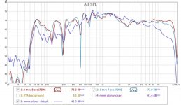
That reading caused me to compare windowed frequency-scan measurements to moving mic measurements, all taken in the vicinity of my listening seat. These are measurements of the planar tower with no equalization, just a 50 Hz high pass to attenuate very low frequencies.
There are two sets of frequency-scan measurements, both displayed with an 8-cycle window applied to the impulse response and no other smoothing. One measurement was made about 2 feet in front of the listening position and the other was made at the listening position. At each of those distances from the speaker I moved the mic vertically from the head height of a seated listener to that of a standing listener and averaged all the measurements made at the same distance from the speaker. About 5 or 6 measurements were averaged in each case. All of the measurements were made on the speaker's main axis.
The moving mic measurement was made in a volume that included both of those locations. I used periodic pink noise and set the RTA mode of Room Eq Wizard to 1/12 octave. I did not restrict my tai chi moves to horizontally---both vertical and horizontal hand-waving within roughly 1 cubic meter.
To ease comparison I offset the RTA measurement to match levels of the two scanned frequency measurements. The agreement looks decent to me, with fewer sharp dips evident in the moving mic result. There's a dip between 2 KHz and 3 KHz in the windowed measurements that doesn't appear in the moving mic results. To fix or not to fix? That is the question. There's also high frequency roll-off in the moving mic result but that included more off-axis mic positions than did the windowed measurements so the roll-off is not surprising.
That roll-off question brings me to the directivity question. I'll address that in another post so these posts don't get too long and too diffuse.
Few
Attachments
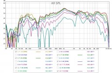
I finally did some directivity measurements and I was pleased with the results. It appears driving the central conductor full-range (above 150 Hz) while driving the two peripheral conductors only from 150 Hz to a few KHz is likely yield the constant directivity result I was hoping for. So far I just have raw data showing that driving the central conductor (which I'll call the tweeter even though it covers a wide bandwidth) spreads the high frequencies much more uniformly than does driving the two peripheral conductors (which I'll call the midrange). I don't yet have the mid-tweeter crossover, or a new set of equalizations to match, but these raw results are very encouraging so I'm sharing them in case someone is interested.
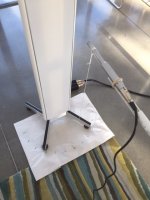
I've attached a photo of the experimental set-up. I didn't want to make a fancy turntable unless I end up doing a bunch of this so I devised a high-tech alternative. I can make one for you if you want to duplicate these measurements but expect to pay a pretty penny. Basically, I marked out an arc around the speaker hung a plumb-bob from the mic, and moved the mic until it was positioned over the desired mark. I used 15 degree intervals, and a 12 inch measurement distance. I realize that's short but I wanted to minimize complications from the signal arriving from distant parts of the tower.
To make the measurements I used a swept frequency, and an 8-cycle window on the impulse response---no other smoothing. I sent the signal either only to the tweeter, or only to the midrange. Both were unequalized, just a 50 Hz high pass filter.
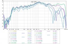
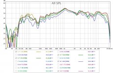
In the first two sets of measurements I show the results from 0 degrees (on-axis) to 90 degrees off-axis, in 15 degree increments. The first set is the tweeter and the second set is the midrange.
Because the results look a bit cluttered, and the 0 to 60 degree range is of particular interest, I'm also showing the same results but over that more limited range of angles.
The main conclusion is that that tweeter's directivity is fairly constant up to the highest frequencies I can hear--and then some. The midrange's directivity is quite constant up to about 2 KHz. Above that frequency the midrange starts to beam. Based on this, I'll try applying a low pass filter to the midrange to attenuate frequencies above 2 KHz, and boost the output from the tweeter above 2 KHz to compensate for the reduced high frequency output of the midrange.
It's an interesting question how quickly I should roll off the midrange. I'd like to avoid funny business at a sharp knee in the response so I may try a more gradual roll-off starting at a lower frequency. This is a different situation than the usual mid-tweeter crossover because I won't be applying a high-pass to the tweeter; just a low pass on the midrange. How do I avoid nasty mid-tweet interferences caused by phase shifts in the midrange output?
Once I get that crossover worked out, I'll have to re-equalize to flatten the response again.
In the meantime, I'm more than a little relieved to find that my central tweeter idea works even without mechanically decoupling the midrange and tweeter diaphragms. That makes construction FAR easier. I went this route because I really wanted to keep the tweeter central (sort of like an MTM arrangement turned on its side) so there wouldn't be complicated and asymmetric horizontal interference patterns from the overlap of the midrange and tweeter outputs. That kind of interference feels like it can't help imaging.
At some point I may try to create fancier looking directivity plots but for now I think these get the main point across. If anyone has a convenient way to display the directivity data please let me know. I have access to, and some familiarity with, Matlab so that's likely what I will explore when time allows.
Few
I've attached a photo of the experimental set-up. I didn't want to make a fancy turntable unless I end up doing a bunch of this so I devised a high-tech alternative. I can make one for you if you want to duplicate these measurements but expect to pay a pretty penny.
Basically, I marked out an arc around the speaker hung a plumb-bob from the mic, and moved the mic until it was positioned over the desired mark. I used 15 degree intervals, and a 12 inch measurement distance. I realize that's short but I wanted to minimize complications from the signal arriving from distant parts of the tower.To make the measurements I used a swept frequency, and an 8-cycle window on the impulse response---no other smoothing. I sent the signal either only to the tweeter, or only to the midrange. Both were unequalized, just a 50 Hz high pass filter.
In the first two sets of measurements I show the results from 0 degrees (on-axis) to 90 degrees off-axis, in 15 degree increments. The first set is the tweeter and the second set is the midrange.
Because the results look a bit cluttered, and the 0 to 60 degree range is of particular interest, I'm also showing the same results but over that more limited range of angles.
The main conclusion is that that tweeter's directivity is fairly constant up to the highest frequencies I can hear--and then some. The midrange's directivity is quite constant up to about 2 KHz. Above that frequency the midrange starts to beam. Based on this, I'll try applying a low pass filter to the midrange to attenuate frequencies above 2 KHz, and boost the output from the tweeter above 2 KHz to compensate for the reduced high frequency output of the midrange.
It's an interesting question how quickly I should roll off the midrange. I'd like to avoid funny business at a sharp knee in the response so I may try a more gradual roll-off starting at a lower frequency. This is a different situation than the usual mid-tweeter crossover because I won't be applying a high-pass to the tweeter; just a low pass on the midrange. How do I avoid nasty mid-tweet interferences caused by phase shifts in the midrange output?
Once I get that crossover worked out, I'll have to re-equalize to flatten the response again.
In the meantime, I'm more than a little relieved to find that my central tweeter idea works even without mechanically decoupling the midrange and tweeter diaphragms. That makes construction FAR easier. I went this route because I really wanted to keep the tweeter central (sort of like an MTM arrangement turned on its side) so there wouldn't be complicated and asymmetric horizontal interference patterns from the overlap of the midrange and tweeter outputs. That kind of interference feels like it can't help imaging.
At some point I may try to create fancier looking directivity plots but for now I think these get the main point across. If anyone has a convenient way to display the directivity data please let me know. I have access to, and some familiarity with, Matlab so that's likely what I will explore when time allows.
Few
Attachments
As a raw measurement that is stellar. Might sound a wee bit bright, but that will be fairly easy to tame with rotation of the cabinet or even a little bit of EQ.
You have done what only a few ( no pun intended ) other companies have succeeded in.
I think you are listening to some very nice sounding loudspeakers.
Thanks very much Mark. I have admit I'm pretty pleased.
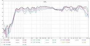
At this risk of pushing my luck, I took a first stab at a mid-tweet "crossover". Again, I'm just low-passing the midrange, not high-passing the tweeter. I'm a bit surprised by the result so I'll stretch everyone's patience by adding it to today's verbosity.
Using my miniDSP, I set a Bessel low pass filter on the midrange to 1 KHz. For some reason there's no way to choose the order of the Bessel---there's just one option. No doubt somebody can explain to me why that is.
In any case, I also added a high shelf to the tweeter to compensate from the lost high frequency output from the midrange. It's a 6.5 dB boost, 1200 KHz, Q=0.5 adjustment.
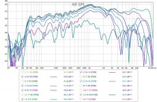
Then I repeated my super-fancy directivity measurements, this time with both the midrange and tweeter driven. The results are attached, first the 0 degrees through 60 degrees measurements, and then the 0 through 90 degree results with vertical displacements to separate them visually. It isn't perfect but...hey, that ain't half bad! This is still with no equalization. Just the 50 Hz high pass on everything, the two filters described above, and 8-cycle windowing on the impulse responses (no other smoothing).
There's a little funny business between 1 and 3 KHz, which of course is right where I'm doing the filtering. Perhaps I can refine that through more experimentation. In the meantime I'll try some overall equalization and some music listening and see how it looks/sounds.
Few
At this risk of pushing my luck, I took a first stab at a mid-tweet "crossover". Again, I'm just low-passing the midrange, not high-passing the tweeter. I'm a bit surprised by the result so I'll stretch everyone's patience by adding it to today's verbosity.
Using my miniDSP, I set a Bessel low pass filter on the midrange to 1 KHz. For some reason there's no way to choose the order of the Bessel---there's just one option. No doubt somebody can explain to me why that is.
In any case, I also added a high shelf to the tweeter to compensate from the lost high frequency output from the midrange. It's a 6.5 dB boost, 1200 KHz, Q=0.5 adjustment.
Then I repeated my super-fancy directivity measurements, this time with both the midrange and tweeter driven. The results are attached, first the 0 degrees through 60 degrees measurements, and then the 0 through 90 degree results with vertical displacements to separate them visually. It isn't perfect but...hey, that ain't half bad! This is still with no equalization. Just the 50 Hz high pass on everything, the two filters described above, and 8-cycle windowing on the impulse responses (no other smoothing).
There's a little funny business between 1 and 3 KHz, which of course is right where I'm doing the filtering. Perhaps I can refine that through more experimentation. In the meantime I'll try some overall equalization and some music listening and see how it looks/sounds.
Few
Attachments
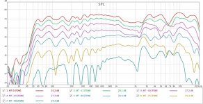
So looking at your horizontal plots i'd say smoothest response with about a 15 degree toe in.
Still looking good.
Polar response
I have used something similar for quite a few years. Try it. You will like it if you are used to listening to live un-amplified instruments.
It gives you a very life like rendering of the music. And if you do both some measurement listening and math you will find that in most rooms this type of a contour will sum nearly to flat response where you listen.
- Status
- This old topic is closed. If you want to reopen this topic, contact a moderator using the "Report Post" button.
- Home
- Loudspeakers
- Planars & Exotics
- DIY planar magnetic + open baffle woofer array