Back with an update!
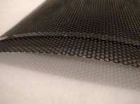
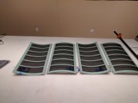
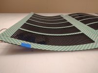
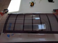
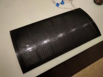
After a week of painting the panels should be pretty well insulated now. I used a last few coats of polyurethane and even just aesthetically the panels look much nicer. I just put 3/4" tape around all of the edges to prevent arcing and to also allow the double stick tape to adhere better to the panels. There is also a little bit of Kapton tape where I soldered the leads on. Speaking of the foam tape, I'm just thinking of using 4056 3M foam tape which is 1/16" thick and 1" wide. This is the same tape that I used in my last build and it is still super tight to this day. Does anyone think that I really need to use VHB tape? I would prefer not to given the cost. In the meantime I might start to build the stretching jig for the mylar. As you can partly see in one of the photos I have a piece of MDF that is formed to curvature of the panels. That was simply a test piece but the plan is to use two of those pieces attached to opposing ends on two bar clamps. There will be some kind of frame to keep everything square, but thats the basic idea. The bar clamps should allow me to apply the same amount of tension in the Mylar for both of the panels by measuring the amount of revolutions on the clamp.
Ben
Attachments
Hi,
the stators look very well executed.
The coating seems very well rounded around the holes and very even.
Before You proceed You may want to test the flashover withstanding capabilities.
btw. the curvature looks less than on the first pics
For the horizontal spacers You may use other materials than the VHB tapes.
They imho justify their higher price tag with convenience, clean working, high performance and not last with their optics.
We are talking about maybe only 10-20$ more cost, which isn't too bad, especially when You compare cost/performance.
The end result will at least perform on par, but probabely better than a dynamic midrange/tweeter pair of highest quality.
Just think how much the premium ScanSpeak and Accuton drivers cost
You may use thin strips of foam tape, plastic strips or silicone rubber band instead.
With plstuc strips and band material just make sure that the thickness is very constant, that it is easy glueable and that You can apply a glue layer of constant thickness.
If You use a hard plastic material make sure that all edges are even and soft and/or covered by (flexible) glue.
Its nearly impossible to get the membrane stick to the curved model evenly without wrinkles if You are working alone on Your own.
The imho easiest and a very reliable way to achieve same tension values is to draw parallel lines on the membrane and the tensioning frame and to adjust for 1.5-2% of elongation.
jauu
Calvin
the stators look very well executed.
The coating seems very well rounded around the holes and very even.
Before You proceed You may want to test the flashover withstanding capabilities.
btw. the curvature looks less than on the first pics
For the horizontal spacers You may use other materials than the VHB tapes.
They imho justify their higher price tag with convenience, clean working, high performance and not last with their optics.
We are talking about maybe only 10-20$ more cost, which isn't too bad, especially when You compare cost/performance.
The end result will at least perform on par, but probabely better than a dynamic midrange/tweeter pair of highest quality.
Just think how much the premium ScanSpeak and Accuton drivers cost
You may use thin strips of foam tape, plastic strips or silicone rubber band instead.
With plstuc strips and band material just make sure that the thickness is very constant, that it is easy glueable and that You can apply a glue layer of constant thickness.
If You use a hard plastic material make sure that all edges are even and soft and/or covered by (flexible) glue.
The curved model plus bar clamps functions very well, but You need help to install the membrane to the rensioning frame....to apply the same amount of tension...
Its nearly impossible to get the membrane stick to the curved model evenly without wrinkles if You are working alone on Your own.
The imho easiest and a very reliable way to achieve same tension values is to draw parallel lines on the membrane and the tensioning frame and to adjust for 1.5-2% of elongation.
jauu
Calvin
Thanks for the compliments Calvin.
How should I go about testing the flashover withstanding capabilities? Should I connect a probe to the bias and the panel to a transformer and see how easily arcing occurs? I'm glad that I can use other materials for the horizontal spacers, but for the main outer perimeter is it necessary to use the VHB tapes? The plan right now is to still use the 4056 foam tape on the panels.
Ben
How should I go about testing the flashover withstanding capabilities? Should I connect a probe to the bias and the panel to a transformer and see how easily arcing occurs? I'm glad that I can use other materials for the horizontal spacers, but for the main outer perimeter is it necessary to use the VHB tapes? The plan right now is to still use the 4056 foam tape on the panels.
I'll be working with another person so it shouldn't be too hard getting the Mylar on without wrinkles.Its nearly impossible to get the membrane stick to the curved model evenly without wrinkles if You are working alone on Your own.
Ben
Last edited:
Hi,
for testing You can connect the stator to the bias supply and use a aluminum household foil as counter electrode that You simply lay on the stator.
Its advantageous to have a bias supply that You can ramp up in voltage.
If flashovers occur You´ll hear that .... low tickling noise usually is irrelevant and tends to decay away after a short period.
It is spread rather randomly over the stator area.
True flashovers are higher in volume and can move the foil.
They can be located by the sound.
In case of very low series resistance values in the bias supply a flashover can hammer´´a small pimple into the foil .. which makles location easy
Start with high resistor values and decrease if required.
You don´t need to use VHB tape for the perimeter.
In fact the foam tapes bond stronger from the very first contact on.
jauu
Calvin
Calvin,
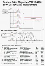
The test with the aluminum foil electrode was not very promising. I started with a piece of foil about 12" x 12" big and placed it on the stator. The buzzing was very audible and the foil was moved a bit. Moving down to a smaller piece the buzzing and movement was tuned down, but not completely eliminated. I don't question the importance of this test, but I conducted the same scenario on my previous speaker and yielded very similar results. I have not had any noticeable problems with arcing on that speaker. The bias supply was built using Jazzman's schematics, which provides 2.7kV DC with a 20 mohm 1W resistor. I have attached the schematics that I used.
Should I be worried about these results even though they are largely the same as my previous panel that was successful?
Ben
Attachments
EDIT: I may have misunderstood your directions. What I did was hook up the stator to one of the connections from the step up transformers and connect the bias to the aluminum foil. If I misread should I have just connected the stator to the bias and lay a piece of aluminum foil on top not connected to anything? I just did that and the foil was laid on top of the stator and only an attraction was apparent as well as a slight buzzing which did go away, but no actual sparks or movement of the foil. Sorry for not understanding your directions I've just never heard of this method (or any method for that matter) to check for flashover capabilities.
Ben
Ben
Hi,
You did the test right. The foil is connected to the bias supply also, so that a electrical field develops between the stator and the foil.
That is exactly the same condition that the membrane will later see.
But as the foil is lowohmic the flashovers develop more energy and they become audible and even become ´hot´ -if the series resistor is also lowohmic.
Then the energy is high enough to move, yet even deform the foil.
Due to the highohmic resistor in the bias supply and the high ohmic membrane coating may the flashovers only be audible at low levels or not at all (in case the membrane touches a stator, which most of the time is luckily not the case).
You may take the HV from an earlier stage of the cascade to evaluate from which voltage level on flashovers become apparent.
jauu
Calvin
Last edited:
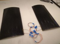
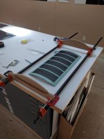
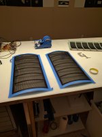
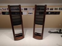
Well the tape arrived today so I put it on the panel's. It's 1" wide so I did a perimeter of that around all the edges and then trimmed the tape to be 1/2" and evenly spaced 5 spars on each panel. They were placed with the other panel in mind so that when they are put together they align just right. Here are two pics of the latest progress.
Ben
Ben
Attachments
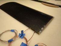
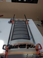
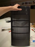
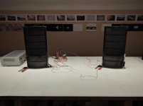
After building the stretcher I finished the panels. I used the bar clamps and shaped MDF so make the Mylar conform to the panel shape. I made marks on the Mylar and went to 1.5% elongation on the 12 micron Mylar. About two hours after the panels were pressed to the Mylar I cut them out using a hot knife and then trimmed the excess Mylar with scissors. I then wrapped electrical tape around all of the edges on the back panels with the Mylar. Then, I put painters tape about a quarter of an inch inwards and then painted the Mylar using the Licron Crystal. After 24 hours I aligned the panels with the Mylar and the panels with the copper charge ring and pressed them together. I did this one panel at a time so that I could use the same formers that were used to stretch the Mylar as bottom spars so that I could put clamps around the edges and weight on the top. Once both panels were put together I fired them up and played some music! There is still a definite sweet spot, but the sound is way more dispersed than my original flat panel. However, I think due to a higher tension and smaller spacing between spars, the sound is not as rich. But as a positive of this on the old panel a really loud drum or bass hit would cause the diaphragm to hit the stator and make an awful sound. So for I've really enjoyed listening to them. In the next few weeks I'll be making frames to hold the speakers and place and make them visually appealing.
Ben
Ben
Attachments
-
 IMG_20160529_143104.jpg475.4 KB · Views: 359
 -
 IMG_20160529_160633.jpg388.9 KB · Views: 336
 -
 IMG_20160529_160643.jpg642 KB · Views: 341
 -
 IMG_20160530_232238.jpg992.8 KB · Views: 289
 -
 IMG_20160529_200143.jpg502 KB · Views: 309
 -
 IMG_20160529_160652.jpg882.4 KB · Views: 337
 -
 IMG_20160530_232254.jpg707.6 KB · Views: 309
 -
 IMG_20160530_234417.jpg768 KB · Views: 346
Last edited:
Hi,
seems that everything came out well ... congrats
From the little Info and by viewing the pics I'd say that the base resonance of the panels should be around 200Hz +-20Hz.
The missing bass would explain the less rich sound.
Also the panel needs quite some break-in time.
Expect several weeks up to half a year before the membrane has settled at its final stable working point.
Heat treatment would reduce settling tome to nearly 0, but is not feasable with the kind of membrane used.
jauu
Calvin
ps: now begins the difficult part ..... finding and mating a matching bass part
Sorry for not posting an update in such a long time, it's been a busy summer!
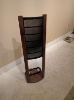
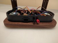
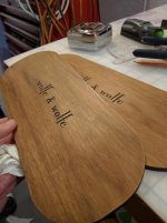
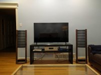
Since my last update the full speakers have been finished with wooden frames and covered electronics boxes. The frames are made out of dark walnut and are tilted backwards a little. Having access to a 3D printer proved essential in the final steps of making these speakers. By making a mock-up of the structure of the frame my dad and I were able to print jigs that would hold the arms that hold the panel to the base at just the right angle while we drilled holes in the arms to accept screws. The black boxes that house the electronics were also 3D printed. Since these speakers were a joint effort and my dad really gets all of the credit for the woodwork we had the lids for the electronic boxes laser-engraved with our last names.
As far as finding a matching bass driver, we took the easiest route. I know that I'll get some hate for this but whatever. The amp we're using is a Sony surround sound receiver bought off of eBay for around $70 that has plenty of power at around 100W for each panel. Because the receiver has a dedicated output for a subwoofer, we just wired the sub from an old LG sound bar. This way there was no need for a crossover. Obviously they probably aren't perfect matches but they seem to work outstandingly together. Eventually I might get around to measuring the panels and sub but that's for another time, and if you guys think that an upgrade in amp would be noticeable that may happen. For music listening I decided to buy a ChromeCast audio and that works really well in terms of quality and convenience.
Attachments
Last edited:


Sorry for not posting an update in such a long time, it's been a busy summer!
Since my last update the full speakers have been finished with wooden frames and covered electronics boxes. The frames are made out of dark walnut and are tilted backwards a little. Having access to a 3D printer proved essential in the final steps of making these speakers. By making a mock-up of the structure of the frame my dad and I were able to print jigs that would hold the arms that hold the panel to the base at just the right angle while we drilled holes in the arms to accept screws. The black boxes that house the electronics were also 3D printed. Since these speakers were a joint effort and my dad really gets all of the credit for the woodwork we had the lids for the electronic boxes laser-engraved with our last names.
As far as finding a matching bass driver, we took the easiest route. I know that I'll get some hate for this but whatever. The amp we're using is a Sony surround sound receiver bought off of eBay for around $70 that has plenty of power at around 100W for each panel. Because the receiver has a dedicated output for a subwoofer, we just wired the sub from an old LG sound bar. This way there was no need for a crossover. Obviously they probably aren't perfect matches but they seem to work outstandingly together. Eventually I might get around to measuring the panels and sub but that's for another time, and if you guys think that an upgrade in amp would be noticeable that may happen. For music listening I decided to buy a ChromeCast audio and that works really well in terms of quality and convenience.
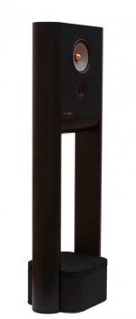
For the woofer you could take some inspiration from the Grimm LS1. It has a similar setup as yours and the woofer at the bottom.
Good job anyway,
Jan
Attachments
Last edited:
....
ps: now begins the difficult part ..... finding and mating a matching bass part
Hi Calvin, I have a question on the bass part and power supply.
1)Typically how would you go about matching a bass unit to such panels? Reason I ask is that some of the earlier ML models had aluminium inverted cone woofers and then later normal cone woofers, etc Would the size of the woofer make all the difference rather than the type?
2) Driedchalk used a toroidal power supply for his panels. Are they prefered to EI transformers?
Thanks!
Hi,
1)
- I ´d look at the distribution character of the panel +-1 oct around the intended crossover and then think about a bass system with similar distribution character. The Panel beeing not so high I assume that the distribution character will be dipolar lobes. This could match with a single dipole bass like a Ripole (if You could drive them high enough in frequency) or a small closed box (maybe with two small drivers dstacked vertically).
- then I´d try to ´visualize if that system looks proper, proportionalized and fits visually to the rest ... all else is probabely up to the electronics
2) To me it rather looks as if he uses the pair toroids for the panel and a different trafo (EI?) for the bias supply. The power toroids prooved to be very good and quite cheap solutions compared to spezialised and costier EI-Trafos. Also, they seem nearly indestructable in this application (sooner or later all my EI-cores died due to internal flashovers). Restriction is the higher lower bandwidth limit, but that is typically no issue if one plans on hybrid ESL anyway.
jauu
Calvin
Last edited:


Hi,
...
2) To me it rather looks as if he uses the pair toroids for the panel and a different trafo (EI?) for the bias supply. The power toroids prooved to be very good and quite cheap solutions compared to spezialised and costier EI-Trafos. Also, they seem nearly indestructable in this application (sooner or later all my EI-cores died due to internal flashovers). Restriction is the higher lower bandwidth limit, but that is typically no issue if one plans on hybrid ESL anyway.
jauu
Calvin
DriedChalk, can you please expound on this? What transformers did you use for the signal/stators?
Calvin, do you have any recommendations? Supplier? I didn't realize these were an option. I too am planning a hybrid design, so this is intriguing!
Thanks!
- Status
- This old topic is closed. If you want to reopen this topic, contact a moderator using the "Report Post" button.
- Home
- Loudspeakers
- Planars & Exotics
- Curved Electrostatic Speaker Build