Hi,
has anyone tried to use a dome driver in a horn designed for compression drivers?
After having seen large horns by Mr.Rudolph be driven by a Dynaudio D54 in the early 80's i tried the same using Ikea 45cm (or so) lampshades and having them fitted with a flange to mount the D54's on. Sound was OK, but i always wondered why it wouldn't go up that much in frequeny as the dome did by itself. Blamed the soft dome and bought Yamaha JA-801 out of wrecked NS1000s later but never got down to try them in those lampshades. Even bought the big Jabo 75cm with alu particle loading years ago and they are still in their original boxes.
My setup is a 10"-driven front-loaded bass horn in corner location and a brace of white whales sittin' on top. I tried lots of comps and have Altec 288G's and EV ND5's with DH1 frams on most of the time. Tried several Beryllium comps like 4002Z, 2435s, 951/Txt fram etc, but wasn't happier than with alu -- that said my single 476Be wasn't tried in earnest as i'm still waiting to get hold of a sibling, and a 4003 is out of range nowadays.
Has anyone here used JA-870, JA-801, JA-802 Be drivers on a horn?
Ralph
Hi sreten,
thanks for the tip-off.
That's quite a comprehensive analysis. Had me thinking about the D54 mentioned above and the D28 and later D21 that accompanied it way back then. A bit later, perhaps in the late 80's or early 90's the "waveguides" that came with the early "Made in Denmark" versions were removed because folks then did not want a "horn" on their speakers. As Zaph pointed out "...be aware that this is not really a horn, it's more of a waveguide." And actually, that is also the difference to my Ikea lampshade. Maybe calling it a "horn" when it wasn't supposed to be one is stretching it, but it certainly was more than 25, maybe even 30cm long. Another line from the article you linked to is "I believe that a horn conversion of this type will not work as well with a long throat horn design". Well, and exactly in what side condition it could be made to work would interest me.
Thanks for the second link also. Seems like a low-buck-for-the-oomph project with such a low level of distortion that it's simply inspiring.
Ralph
Note that adding a horn with a throat the same side as a direct radiator doesn't change the compression ratio. It only changes the radiation pattern versus frequency.
Yes, true, but not sure which direction you want to go with this (EDIT: not meant rudely at all, pls apologize if it sounds like it on first reading). The article linked to above had on-axis response flatness, on-axis distortion, and amplitude directivity as a focus. The on-axis time-domain graphs changed quite a bit, but there was no "floor" adjustment that would nod towards the increased on-axis sensitivity. Maybe or maybe not because of this, the author did not really elaborate the topic except (perhaps?) when doing the sideline on *real* horns, i.e. "as that pretty much requires a compression driver, and lots of other problems are introduced that are typical of horn systems".
So, big Q then would be, does it require a compression driver to introduce all those "other problems", or can it also be done by a dome without using compression? Cheeky.
Seems a comparison of same driver used with and without compression into a like expansion would be needed (??)
Ralph
Last edited:
Well, no interest stirred, it seems. Hence lazyly on my end ...
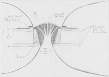
I made a dirty hand-drawing of the arrangement i had in mind.
Horns should not necessarily need to be mounted simultaneously")
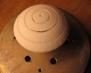
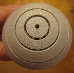
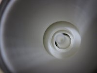
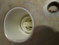
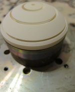
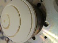
Also attached pics of two similar phaseplugs i had made in polyamide and alumide plus their results with a Selenium 1.4" plastic horn.
Plugs are slightly different in progression of the air channels. Channel location is same.
Next will be some variation of the channel entry location under the dome.
Ralph
I made a dirty hand-drawing of the arrangement i had in mind.
Horns should not necessarily need to be mounted simultaneously
Also attached pics of two similar phaseplugs i had made in polyamide and alumide plus their results with a Selenium 1.4" plastic horn.
Plugs are slightly different in progression of the air channels. Channel location is same.
Next will be some variation of the channel entry location under the dome.
Ralph
Attachments
-
 JA-801_as_horn_driver.jpg927.9 KB · Views: 307
 -
 JA801-2_Phaseplug 002.jpg97.6 KB · Views: 296
 -
 JA80xPhasePlug4 007.jpg153.9 KB · Views: 291
 -
 JA80x mod Phaseplug.jpg288.8 KB · Views: 292
 -
 JA801-2_Phaseplug 005.jpg384.8 KB · Views: 287
 -
 JA802_WhitePlug_min_distance.png30.7 KB · Views: 104
 -
 JA802_GrayPlug_low_distance.png31 KB · Views: 85
Last edited:
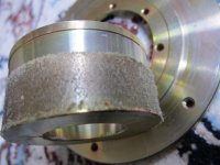
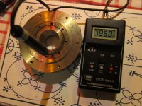
Next (fifth, actually) iteration did arrive today. Haven't measured it yet, as this one is wee bit shorter in order to accomodate for a trial using 20mm high N52 "tablets" instead of the original 25mm high ferrite ring. That ferrite delivers about 1.7T on average of several JA-801/802's measured. Same as JA-6603 or JA-6681 ferrites do using smaller ferrite but narrower gap.
Quite nice, given the gap accomodating the coil is *very* wide (sooo wide my cheap'n'cheerful Chinese HT20 fluxmeter's probe just fits in). Printing quality of this "MX3" material is better than the Polyamide (which was better than the Alumide). All nice then, but the Neo tablets seem to be stuck in Amsterdam acc to tracking info. Hope they're not stuck to the wall of the carrier craft for good
Anyways, will post ARTA results here once the thing speaks...
Charah,
Ralph
Attachments
Last edited:
Alright, a pair is completed and magnets for another pair are already here. Results are a bit of a mixed bag...
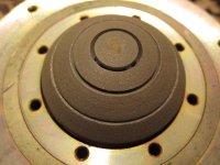
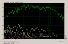
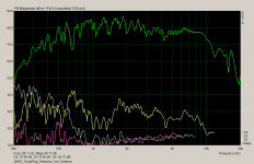
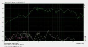
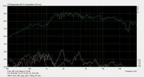
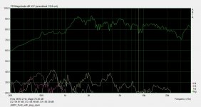
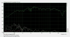
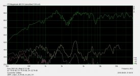
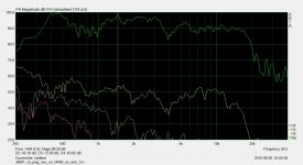
Field strength went up to ca 1.9 T, and with more B you get more high-range output. This is very evident in the three measurements i did on the "normal end" (i.e. dome side) of the Yamaha JA-801. The phase plug was in place. Remember, the JA-802's would even reach slightly higher up due to lower moving mass. A fourth shot shows the dome side again, but with the orig. fiberglass stuck up the 'plug and the orig. metal cap (incl it own fiberglass filling) fitted over the plug output on the rear of the magnet.
Also attached in next post is a graph measured on axis, but mounted on a horn, SPL is good til 17kHz. This is on a 55x29cm EV horn -- not the 39x19cm exit Selenium horn as above
Attachments
Last edited:
The dip visible just below 4 kHz in some of the plots might be attributed to a resonance in the magnetic system. The neo magnet is totally undamped internally and offers a ca 26mm path from voice coil to the magnet backplate and also (through eight 7mm-holes in the top plate) a ca 30mm long path from suspension to the magnet backplate. The original ferrite magnet has a layer of 1cm wide and 1.5cm high foam around the pole piece (and hence behind the vc and the suspension ventilation holes).
Why do i get lower output below 1.2 kHz as compared to ferrite? Fellow ETF'er Dietmar experimented with home-rolled compression drivers quite a bit. His guess is that the volume behind the coil/suspension is too big. I bought polyester resin and will fill the magnet right up to the top plate. Will post response graphs again if the lower end improves. My hope is for at least the 3.8 kHz resonance to disappear after that mod...
Why do i get lower output below 1.2 kHz as compared to ferrite? Fellow ETF'er Dietmar experimented with home-rolled compression drivers quite a bit. His guess is that the volume behind the coil/suspension is too big. I bought polyester resin and will fill the magnet right up to the top plate. Will post response graphs again if the lower end improves. My hope is for at least the 3.8 kHz resonance to disappear after that mod...
Attachments
Last edited:
A standing wave resonance at 3.8kHz would require a path around 45mm in lenght, that would make a chaber Resonnance trough some kind of resonator Volume more likely then a standing wave according to the given dimensions. Are there anny volumes that could couple through something that could qualify as a tube? The backchamber/coil gap maybe?
Greetings, 3ee
Greetings, 3ee
The "backchamber/coil" thing is what i was looking at. Those are 24mm and 30mm (48 / 60 both ways). Not sure what could be 45mm long single way (or 90mm both ways). The way through the phase plug itself would qualify. But that is an open ended pathway.
The two ways i was thinking of are under scrutiny, as i filled up the empty space inside the magnet altogether with resin.That will allow a backwave to the coil or suspension only beyond the audible range.
Unfortunately, some of the resin got into the gap and i haven't found the time to scratch out that seriously hardened stuff. Will run some meas once that's done.
1) you can´t because you have:
a) a soft dome, while given thigh pressures involved requires a hard one.
No surprised the historical dome evolution, in compression drivers, was thickly impregnated phenolic cloth or some kind of plastic > aluminum > Titanium , while you go backwardsbto soft cloth domes.
b) you lack a "phase plug" or "compression chamber" to really rise efficiency and at the same time keep a reasonable response without self cancellations.
2) and if you add a hard dome and a compression chamber/plug you are now *building* a standard compression driver, just using a recycled magnetic circuit pulled from a soft dome
Three more designs were made in the last twelve months. Aim was to find out if there are audible fundamental traits to three of the 6 or 7 fundamental phase plug design "schools".
Each time, my chosen Yamaha soft dome motor (in modified form with 3/4" high NdFeB pills) was chosen. That yields two advantages:
a) independence of the variance that i encountered with non-centric backplate mounting on the many a stock Yamaha JA-870/JA-0801 driver magnet structure
b) ca 6mm shorter path from the Beryllium into the horn's throat.
If it wasn't for a), i would have given in to requests to make one of the earlier annular long versions available for the orig. ferrite structure available for order directly from rapidobject or 3D-Hubs, where i found great support for my model's "issues". Having 20 or so of the Be-domes, that admittably limited statistical sample size would lead me to say your chance getting a suitable mag is 15%. Another 15% allow mounting of the phase plug with an hour's worth of manual labor with a standard iron file, tape on gap
An new interpretation of Henricksen's (some say Hilliard's) radial design with a bit of annular thrown in for good measure:
Here's the take on the saltshaker aka pepper pot. Channels tapered. Also not straight as in the pioneering originals. So easy to do with additive manufacturing...
Each time, my chosen Yamaha soft dome motor (in modified form with 3/4" high NdFeB pills) was chosen. That yields two advantages:
a) independence of the variance that i encountered with non-centric backplate mounting on the many a stock Yamaha JA-870/JA-0801 driver magnet structure
b) ca 6mm shorter path from the Beryllium into the horn's throat.
If it wasn't for a), i would have given in to requests to make one of the earlier annular long versions available for the orig. ferrite structure available for order directly from rapidobject or 3D-Hubs, where i found great support for my model's "issues". Having 20 or so of the Be-domes, that admittably limited statistical sample size would lead me to say your chance getting a suitable mag is 15%. Another 15% allow mounting of the phase plug with an hour's worth of manual labor with a standard iron file
, tape on gapAn new interpretation of Henricksen's (some say Hilliard's) radial design with a bit of annular thrown in for good measure:
An externally hosted image should be here but it was not working when we last tested it.
Here's the take on the saltshaker aka pepper pot. Channels tapered. Also not straight as in the pioneering originals. So easy to do with additive manufacturing...
An externally hosted image should be here but it was not working when we last tested it.
- Status
- This old topic is closed. If you want to reopen this topic, contact a moderator using the "Report Post" button.
- Home
- Loudspeakers
- Planars & Exotics
- Converting dome to comp driver