What a turn! Dump the speakers! Use headphones!
Household consumption is a small part of a total one. So called green products like solar panels and electric vehicles waste more energy during production then save.
My note was just technical i.e. need for yet higher voltage to feed the final stage. I do not see anything wrong with coupled inductor or center-tapped auto-transformer as a load. With proper deigned feedback it will work without dummy load.
I do not see anything wrong with coupled inductor or center-tapped auto-transformer as a load. With proper deigned feedback it will work without dummy load.
You see nothing wrong? I guess you've never compared the input to the output of a 1:100 ESL interface transformer. The system input needs a lot of massaging to make the amp happy with the input impedance it sees and the cells happy with the output voltage frequency response driving them.
Granted, a hybrid design with a 1:10 step-up might not be as screwy.
Ben
@bentoronto
The part of my job is to design magnetics. Without a proper execution it would not work and regular meticulous winding is the least problem, especially at few kV. However if you pick up feedback from anodes instead of output winding you definitely remove rather complex transformer's transfer function from the loop. So it's easier. Capacitive load is always a challenge for voltage source thing like amplifier. Anyway there is nothing wrong in using amp as suggested in the article. 1:10 Xformer is more complex than 1:10 - you have two HV windings.
Tubes in that respect are much more robust then FETs, unless you use HV radio transmitter ones which are designed for such abuse namely SWR. 1200 Vds is the max you can get. Like tubes they are prone to oscillation which is fixed the very same way: adding lossy inductor to the grid or gate for that matter. However like pentodes they could form current source with no feedback from the output whatsoever using cascode. All you need then will be servo to hold half of DC bus at the outputs.
As Calvin mentioned besides the efficiency issue resistive loaded stage does produce lesser voltage. So despite added complexity SRPP is probably as best as you can get for such a task.
For instance IXZR08N120A or ARF465 without exotic ceramic packages. It's not exactly cheap but definitely less than a transformer. 2000 V p-p is probably not as bad in regard to sound pressure level.
Cheers, Alex
Almost forgot: going above 1000 Vrms you will see secondary effects coming like traking partial discharge and so on and so forth.
Last edited:
Don't think I understood a word of previous post. My loss, of course. I think you were defending the use of transformers.
But I would point out that all the conventional tube audio amps I know of, have feedback from the secondary of the output transformer. Must be there in order to correct shortcomings of the transformer.
On the other hand, never heard of ESL 1:100 transformers using feedback because of the high voltages, I suppose. Maybe they should or maybe the feedback correction is real but small. Since ESLs sound so good, maybe nobody cares too much to make the transformer perform better.
So I conclude using a transformer without the possibility of feedback around the transformer, has limitations and direct drive, as I have experienced it, is certainly great.
Ben
Transformer inserts non-linearities as well as phase shifts and resonances. Moreover without the load the resistance seen by the tubes could be really high and sometimes resonance peak could not be handled by amplifier: it will oscillate.
I suggested to pick up feedback from plates thus eliminating over mentioned problems. Then you do not need dummy load.
I suggested to pick up feedback from plates thus eliminating over mentioned problems. Then you do not need dummy load.
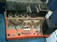
Checking out some old photos.... here's my direct drive amp. B+ of 2400v. Lethal. That loose resistor at bottom is for shorting-out any residual voltage when working on the amp.
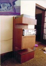
The other picture is a component cabinet I made in 1978. On the top was a straight-line tracking turntable on a seismic platform and well-sealed from room acoustics.
The box at the bottom was for the amp. No kidding. The little black line at the top of that box is the air vent. The amp provided a low and adjustable voltage for a quiet muffin fan. The jack for the fan is near the grey knob that adjusts the HV panel bias.
Worked great for decades, first driving some panels I made from surplus Dayton-Wright cells* and then driving genuine DW speakers. Sold it maybe 15 yrs ago.
The general mirror-image circuit configuration followed Sanders. But the large array of brown power resistors you see is really what the amp was driving; the panels just sort of along for the ride. Some effort making the Sanders circuit stable and that was the solution.
I think transformers are much more of a weak-link for driving ESLs than is ordinarily supposed (because they look so innocent on circuit diagrams). I think you'd be dismayed if it were possible to chart the signal that comes out of an ESL transformer to drive a panel. But transformers are actually much better elements for coupling and hum-avoidance elsewhere in a circuit than is supposed too.
Ben
*these make me exceedingly delighted every day now, playing north of 130 Hz.
Attachments
Last edited:
Never crossed my mind. Resistors are pretty well behaved elements.Ben, have you tried to use inductors instead of ballast load resistors?
Do you have some reason to think it would be beneficial?
B.
I don't know enough to credibly doubt your post.efficiency betters alot, as the voltage swing using a inductor as anode load can nearly be doubled.
Seen the other way ... one could reduce the supply rail voltage to nearly 1/2
But, I dimly recall getting an output like 750 v rms which comes pretty close to all you can get from a 2400 v rail. And the amp was flat and clean from very low to very high.
I should mention that the amp did make loud music but did not drive the speakers as loud as lovers of Mahler symphonies might like on party night. But then again, the Dayton-Wright cells are piggish about needing drive voltage.
And the B+ in a direct connection adds to the HV bias (which, of course, has to be minus).
Wonderful to aim for efficiency. Direct drive amps and ESLs are pretty efficient compared to the some of the monsters advocated on the sub forum. Or maybe it is just Toronto climate that makes me happy with vacuum tubes and a bank of hot resistors.
B.
Hi,
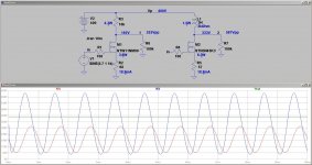
regarding R- versus L-loading see attached pic.
It prooves that the anode voltage with an inductie anode load can easily swing beyond the supply voltage.
Both MOSFETs are set to the same idle current bias points and receive the same input signal.
"Direct drive amps and ESLs are pretty efficient compared to..."
Well they become pretty inefficient towards the upper audio bandwidth too.
If You design for full power bandwidth at 20kHz You end up with several hundreds of W to a kW of mostly wasted power.
jauu
Calvin
Attachments
Hi all,
... just to let out an idea that has been simmering for some time now ... how would it be with a DSD direct power amp - e.g. a DSD512 amp directly driving an electrostatic panel, and where the panel could be part of a suitable RC low pass filter ... ? Might it be feasible while considering needed rise/fall times?
Cheers,
Jesper
If You design for full power bandwidth at 20kHz You end up with several hundreds of W to a kW of mostly wasted power.
... just to let out an idea that has been simmering for some time now ... how would it be with a DSD direct power amp - e.g. a DSD512 amp directly driving an electrostatic panel, and where the panel could be part of a suitable RC low pass filter ... ? Might it be feasible while considering needed rise/fall times?
Cheers,
Jesper
Last edited:
.........
"Direct drive amps..." ... become pretty inefficient towards the upper audio bandwidth too.
If You design for full power bandwidth at 20kHz You end up with several hundreds of W to a kW of mostly wasted power.
jauu
Calvin
That's concerning. Thanks for the tip off. Do all Direct Drive amp designs do that?
So called green products like solar panels and electric vehicles waste more energy during production then save.
Actually I asked an expert (Rene van Swaaij from the Delft University of Technology) about that once and he wrote to me that it typically takes 1.5 to 4 years before the energy used in production of solar panels is gained back. The typical lifetime of these panels is much more than that.
Hi,
Yes and No")
As the amp needs to supply for the required amount of load voltage and current You can easily calculate the ´demand´ of the load.
The formula reads Ip = (Cload + Cx) x pi x f x Vpp with Ip: peak load current, Cload: capacitance of the connected ESL, Cx: other capacitaces from cabling etc, pi: 3.14, f: frequency of the driven signal Vpp: peak-to-peak signal voltage
Larger non-segmented sheet metal panels (curved, hybrid) show capacitance values around 1nF and can take up to ~6kVpp
Segmented wire stators can be as low as 100pF but typically demand more voltage, say up to 10kVpp.
Cx can be chosen to 50-100pF.
f is chosen 20kHz for full power bandwidth.
For the non-segmented ESL the chosen values result in Ip~420mA peak.
Powered by a bridged amplifier the supply voltage of the amp needs to be at least a bit higher than 3kV, giving 1.26kW
For the segmented ESL the chosen values result in ~130mA peak.
For 6kVpp it´d be ~75mA peak, giving 1.3kW, resp. 450W.
The amp needs to supply for huge amounts of peak power.
Now the efficiency depends on the circuit topology and bias class in first place.
A single ended amp where the anode load is a resistor needs class-A biasing and achieves a maximum efficiency of only 12.5%
A single ended amp where the anode load is a inductor or a constant current source needs class-A biasing and achieves a maximum efficiency of 25%
A single ended amp where the anode load is a inversly modulated constant current source (SEPP) needs class-A biasing and achieves a maximum efficiency of 50%.
The same efficiency as a true pushpull output (complementary or quasi-complementary doesn´t mater) stage achieves when biased in class-A.
That is without taking the preamplifying stages of the amps and the power supplies into account.
A pushpull stage biased in class-B (or AB, however one defines) can typically achieve ~70%, power supply included.
class-D switching stages while theoretically beeing able to achieve even higher efficiencies will be HF transmitters and won´t comply with emv regulations.
So, practically its almost impossible to drive a non-segmented ESL actively and achieve a full power bandwidth of 20kHz.
All Amps I know of are designed for lower FPBw.
5kHz seems a sensible limit as music usually doesn´t contain much large signal content above 5kHz.
Due to f forming a linear part of the above equation, the peak current reduces to 1/4 of the 20k value.
Still though we´re talking about amps of the multi-hundred-Watts class.
And so far one hasn´t wasted a thought about heat and safety issues.
For safety it´d be best when the whole amp be´d encapsulated ... even without external cabling ... but for best heat radiation a highly open design would be fine.
jauu
Calvin
Yes and No
As the amp needs to supply for the required amount of load voltage and current You can easily calculate the ´demand´ of the load.
The formula reads Ip = (Cload + Cx) x pi x f x Vpp with Ip: peak load current, Cload: capacitance of the connected ESL, Cx: other capacitaces from cabling etc, pi: 3.14, f: frequency of the driven signal Vpp: peak-to-peak signal voltage
Larger non-segmented sheet metal panels (curved, hybrid) show capacitance values around 1nF and can take up to ~6kVpp
Segmented wire stators can be as low as 100pF but typically demand more voltage, say up to 10kVpp.
Cx can be chosen to 50-100pF.
f is chosen 20kHz for full power bandwidth.
For the non-segmented ESL the chosen values result in Ip~420mA peak.
Powered by a bridged amplifier the supply voltage of the amp needs to be at least a bit higher than 3kV, giving 1.26kW
For the segmented ESL the chosen values result in ~130mA peak.
For 6kVpp it´d be ~75mA peak, giving 1.3kW, resp. 450W.
The amp needs to supply for huge amounts of peak power.
Now the efficiency depends on the circuit topology and bias class in first place.
A single ended amp where the anode load is a resistor needs class-A biasing and achieves a maximum efficiency of only 12.5%
A single ended amp where the anode load is a inductor or a constant current source needs class-A biasing and achieves a maximum efficiency of 25%
A single ended amp where the anode load is a inversly modulated constant current source (SEPP) needs class-A biasing and achieves a maximum efficiency of 50%.
The same efficiency as a true pushpull output (complementary or quasi-complementary doesn´t mater) stage achieves when biased in class-A.
That is without taking the preamplifying stages of the amps and the power supplies into account.
A pushpull stage biased in class-B (or AB, however one defines) can typically achieve ~70%, power supply included.
class-D switching stages while theoretically beeing able to achieve even higher efficiencies will be HF transmitters and won´t comply with emv regulations.
So, practically its almost impossible to drive a non-segmented ESL actively and achieve a full power bandwidth of 20kHz.
All Amps I know of are designed for lower FPBw.
5kHz seems a sensible limit as music usually doesn´t contain much large signal content above 5kHz.
Due to f forming a linear part of the above equation, the peak current reduces to 1/4 of the 20k value.
Still though we´re talking about amps of the multi-hundred-Watts class.
And so far one hasn´t wasted a thought about heat and safety issues.
For safety it´d be best when the whole amp be´d encapsulated ... even without external cabling ... but for best heat radiation a highly open design would be fine.
jauu
Calvin
Anyway, the last link on this page links to the schematic and design report of my high-voltage amplifier:
Elektrostatic Loudspeakers
Over most of the audio range it supplies a frequency-independent voltage instead of a frequency-independent current because the crossover filter of Frank Verwaal's loudspeakers took care of the conversion from voltage to current. Unfortunately, that meant that most of the signal power was used for heating up his crossover filter.
The amplifier was quite inefficient, it sounded very beautiful, and overall it was completely useless because the clipping LED would turn on on anything but soft background music.
Do you include dust removing effort as well as sun tracking mechanotronics? What about real life inverter and batteries. How much is for the ones with 10 years life span without repair. Still it's more than reasonable where central grid is absent - no need for fuel delivery/storage to begin with.Actually I asked an expert (Rene van Swaaij from the Delft University of Technology) about that once and he wrote to me that it typically takes 1.5 to 4 years before the energy used in production of solar panels is gained back. The typical lifetime of these panels is much more than that.
Cheers, Alex.
Since the losses are ~V square - switch mode amplifier, even quasi-resonant/ class E without that much of a noise will not do, especially if the load is tens of milliamps.Hi,
fast switching generates HF noise.
fast switching of large amplitudes generates tons of HF noise.
It'd be hard maybe even practically impossible to comply with emc/emv regulations.
jauu
Calvin
- Home
- Loudspeakers
- Planars & Exotics
- Any Direct Drive ESL Amp projects someone could share?