I have been an admirer or planar magnetic drivers for longer than i care to remember. I will not go into WHY i like them...everyone has a soft spot!
Through the years i have acquired different speakers utilizing this kind of drivers from USA, Japan and Europe...
As this has progressed into a minor obsession i started to buy drivers (mainly from ebay) other times to use them in my diy speakers and others -especially when they were destroyed- just to open them up and study their construction...great school into the whys and hows and don't s of making them...
Makers include Infinity, Fostex, Quadral, Sawafuji, B&G, Monsoon, LFT and various obscure Chinese vendors...
Why now, you may ask?
Well, after paying a large sum to have the 4 mid planars of my speaker redone by the factory- and also being informed that the replacement foils left, are counted in the fingers of one hand... i have decided it was time to try to make my own driver.
I have amassed -i think- enough data to start a dedicated project.
I would like to keep it under perspective though...i am aiming at a specific
kind of driver that could be easily used in a three way speaker.
Meaning that the bass has to be covered by a woofer and the higher registers by a ribbon tweeter.
Arrays are definitely in the equation!
The main question was this: how low does it have to go?
I said to myself that i would be happy if it could play as low as 150Hz...
Meaning that it will have sufficient output a little higher...say 200-250Hz making crossover options a bit more liberal ...
On the other end would love to be able to cross it at 4-5KHz...to a ribbon tweeter of course!
Parameters like size, shape, foil construction, tension, magnets, magnetic gap etc etc i will have to deal with on the way.
Seeing that most famous mid planars have an exposed area from 50X70mm to 65X150mm and that they have limited use under 500 Hz, i opted for something larger.
I will not go into the extremes of the mid bass drivers of the past like Infinity L-EMIM, Fostex FS40 and FS41 or even the newer smaller version of the L-EMIM used in the IRS Epsilon.
Those where from around 25 X 50cm drivers down to 20 X 40cm.
I will make it a bit more elegant ... something like 15-18X23-30cm and if the bass extremes are not reached i will have to stack them.
We are living in a great era where machining can be programmed, magnets can be bought cheaply and you can buy the foils in rolls.
I am open to discussion...
Last edited:
well i thought to do a rerun on just such a driver. ")
My take on it would be opting for line aray from start since its a good way to maximize area, get efficiency, and maked it able to use a thicker and longer conductor hence higher power handling. i propose push pull system max width of 10cm and around 120 cm tall(or taller), and the use of rubber magnets, (yes like magnepan)
only downside... this system for mid high freq will stand or fall by the size of the rubber magnets. i once did a thread on making simple planars with original magnepan magnets cut in half. this would result in ~3mm wide strips that where around 2 mm in thickness. because they are so small, i was able to put allot of driven areas versus non directly driven area on the membrane. they sounded rather nice, for the knowledge i had back then.
The idea of doing a retake just started a month ago so its funny you mention .
So major problem in my opinion for my design would be getting the magnets made or slit. The existing and affordable ones are 12mm.
or the wider versions witch is prob more easy to slit or procces on a plotter (heavy one that is)
a friend of mine already informed for custom sizes in indie so far no luck , all manufactures have 12mm as there smallest. so its either slit yourself or let china extrude one special for you witch ofc comes at a price.
this sort of principle is also used on the Magnepan tymp 1d tweeters witch cross at 1 khz i believe. but could be crossed lower. when you would make them larger
they could be crossed lower, because you can use a thicker conductor. the 1d tweeters could reach lower, but at risk of burning.
with a width of 10 cm beaming would start at 3450 Hz i believe, or am i forgetting something.... maybe i have to look that one up
good dispersion according to Fikier up to 90 degree that would be 1/3 the wavelength , so good dispersion up to 1150 hz. thats to low, so radiating area should be slimmer than that.
My take on it would be opting for line aray from start since its a good way to maximize area, get efficiency, and maked it able to use a thicker and longer conductor hence higher power handling. i propose push pull system max width of 10cm and around 120 cm tall(or taller), and the use of rubber magnets, (yes like magnepan)
only downside... this system for mid high freq will stand or fall by the size of the rubber magnets. i once did a thread on making simple planars with original magnepan magnets cut in half. this would result in ~3mm wide strips that where around 2 mm in thickness. because they are so small, i was able to put allot of driven areas versus non directly driven area on the membrane. they sounded rather nice, for the knowledge i had back then.
The idea of doing a retake just started a month ago
so its funny you mention .So major problem in my opinion for my design would be getting the magnets made or slit. The existing and affordable ones are 12mm.
or the wider versions witch is prob more easy to slit or procces on a plotter (heavy one that is)
a friend of mine already informed for custom sizes in indie so far no luck , all manufactures have 12mm as there smallest. so its either slit yourself or let china extrude one special for you
witch ofc comes at a price.this sort of principle is also used on the Magnepan tymp 1d tweeters witch cross at 1 khz i believe. but could be crossed lower. when you would make them larger
they could be crossed lower, because you can use a thicker conductor. the 1d tweeters could reach lower, but at risk of burning.
with a width of 10 cm beaming would start at 3450 Hz i believe, or am i forgetting something.... maybe i have to look that one up
good dispersion according to Fikier up to 90 degree that would be 1/3 the wavelength , so good dispersion up to 1150 hz. thats to low, so radiating area should be slimmer than that.
Last edited:
It's good to know that someone else is torturing his mind with the same problems...
TBH magnets are not a problem: I have a reliable source in China that i have used many times for custom shapes.
The driver is going to be isodynamic...so magnets on both sides for equal and steady drive.
I will deal with all the problems that plague this kind of drivers...and i have spotted a few!
How much is beaming a problem if you make for example a 1 meter long array out of multiple units...say 4 pcs, and your listening spot is approx 4 meters away?
I am a critical listener and always sit on the sweet spot - no hopping around!
length is not the issue for beaming. its the width.
isodynamic, well as i said push pull it does not mater if it are multiple units or just one.
the wider they are the smaller the sweetspot. if ur ok with sitting always on that one chair in the same position. then go with wider. and dont worry about dispersion.
isodynamic, well as i said push pull
it does not mater if it are multiple units or just one. the wider they are the smaller the sweetspot. if ur ok with sitting always on that one chair in the same position. then go with wider. and dont worry about dispersion.
I have worked on a design for the foil.
Using around 20 micron thick trace and about 1.5mm wide i can get a 7 Ohms impedance.
I have a limit to the kapton pieces that i have so it can't be more than 19X26 cm at the moment.
If i work on it a bit harder i will surely make it an 8 Ohms one.
It's just a matter of adding trace length...but i will not go any less than 1.5mm wide.
I want it to be able to stand 100 Watts...
Last edited:
About the same thickness if i remember well...0.25mm or something.
When i talk about 19 cm width...it is the WHOLE width the sheet has.
I need at least 1 cm per side so i can tension it properly...so 17cmX24 cm max.
Deduct from that the frame and the non exposed part of kapton and that leaves roughly 10 cm of width...
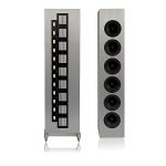
My design has 8 openings (9 rows of magnets) about 8mm wide each.
If i could get as much as almost double the length i would be happy...but probably i will end up with an exposed area of 10-10.5 cm X 18-19 cm.
Mated with a custom tweeter with the same exposed length...side by side...perfect array...something like the photo...
When i talk about 19 cm width...it is the WHOLE width the sheet has.
I need at least 1 cm per side so i can tension it properly...so 17cmX24 cm max.
Deduct from that the frame and the non exposed part of kapton and that leaves roughly 10 cm of width...
My design has 8 openings (9 rows of magnets) about 8mm wide each.
If i could get as much as almost double the length i would be happy...but probably i will end up with an exposed area of 10-10.5 cm X 18-19 cm.
Mated with a custom tweeter with the same exposed length...side by side...perfect array...something like the photo...
Attachments
Last edited:
I'm really interested in this. Subscribed. Like the design goal.. 200-4k.
Low impedance amplification is no problem I think so this I believe should not be hindering. 4 ohm resistive no problem - even 3 is ok.
Open also backwards (bipol).
I have incoming magnets for ribbon of size 150x10x4 mm with N/S coming out of the 4mm side - here it should be the 10mm side I believe?
//
Last edited:
OK but I want an even field for the ribbon. I have a feeling that for a planar with a carrier for the traces and much higher mass/stifness this is less critical.
I'm set to build myself a pair of these so I will follow this. Specifically if you can create good foils I would be interested to buy a set if you would share them.
Would you care to show more of the driver design? Im really curious about it. Can the Neo10 be improved on?
Here is the start of my ribbon: http://www.diyaudio.com/forums/plan...-son-geriitts-reductio-ad-minimum-ribbon.html
//
better is to use as thin as possible. better against cavity resonances
+1 (I think
=I have made a couple CAD designs with small variations. A "just mid" planar is easy to make. I have designs ready that i'm pretty sure they will work perfectly. The problem is to strike a nice balance so as to make a hybrid between a low-mid and a bona fide mid planar. The LFT-10 from Eminnent Tech is almost there...
If it was just a bit larger it would have fitted my needs perfectly...
If it was just a bit larger it would have fitted my needs perfectly...
Funny its a bit dated considering the ceramic magnets.. but hell it works. on the other hand absolute nothing is new to this design. almost all planar speakers that are push pull look like this from the top
what is new is:
Magnetic field focussing channels? should model that in femm to see if it does anything
they use mylar instead of kapton, heat handling is beter in kapton no doubt. but its hard to find anything thin that comes close to mylar.
@ TNT ah you make a normal ribbon then discard my comment on the magnets, its more aboutthe planar
what is new is:
Magnetic field focussing channels?
should model that in femm to see if it does anything they use mylar instead of kapton, heat handling is beter in kapton no doubt. but its hard to find anything thin that comes close to mylar.
@ TNT ah you make a normal ribbon then discard my comment on the magnets, its more aboutthe planar
OK - there is a distinct cavity and there are slots. These two aspect should drive a lot of what can be accomplished. The dimensions govern by magnets, efficiency and area (area fixed when freq and spl set)
Whats your view on cavity ans slots. How much influence do the slots have? Why are almost all, if not all, cavities use 90 deg corner angels when this form a perfect resonance chamber?
//
Whats your view on cavity ans slots. How much influence do the slots have? Why are almost all, if not all, cavities use 90 deg corner angels when this form a perfect resonance chamber?
//
OK - there is a distinct cavity and there are slots. These two aspect should drive a lot of what can be accomplished. The dimensions govern by magnets, efficiency and area (area fixed when freq and spl set)
Whats your view on cavity ans slots. How much influence do the slots have? Why are almost all, if not all, cavities use 90 deg corner angels when this form a perfect resonance chamber?
//
well why i dont know, i guess cheaper. also with the new neo's magnets can be flatter so smaller cavity's. i dont hink the cavity's are a huge problem, its just a thing to think about. you dont need thick magnets, because efficiency with neo's in a push pull config is usually not a problem. also les magnet is needed so its cheaper
@TNT :they do play a part but i would not loose much sleep over them.
I have seen very accomplished drivers with as much as 12mm deep slots (magnets and plate).
It's one of the problems to address though when designing something like this.
Trying to make the magnets as thin as possible is one aspect.
"Chamfering" the exit edges of the steel plate to reduce the depth of the canal is another.
I also have some ideas about the covered part of the foil (the one that doesn't "see" through the slits) at the edges.
This should definitely be treated in some way or configurated so that it doesn't promote standing waves.
I am also thinking of using slightly thicker plates and CNC into them (1-2mm deep) the magnet positions.
This would also act as Thigpens magnetic force "channeling".
Plus... it would end the old problem of magnets detaching and destroying the foil...
- Home
- Loudspeakers
- Planars & Exotics
- My own magnetic planar driver