First of all why ?
well i ran into some problems with the following jigs.
1. Tape..... well just plain random.
2. Tire Jig, nice but somehow loses tension, either tape is or the tire is. also when heat treated membrane the jig wont pull it straight to the required tension but the mylar just slacks.
3. weights clamps and pulleys. this is the one i am after but!, i want it to be easy in use. and the option of automation the opening of the clamps. there is no fun in opening 40 clamps and putting the mylar in one by one. further to much pulleys that are expensive, and to much weight needed. lead is still not insane cheap so i would love to not spend 100 euro on weight.(ofc this depends on your application, if you need to make allot and money is no issue hell yeah !)
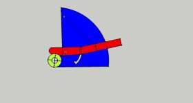
Dont mind my shitty modeling skills") but i hope i can explain what happens.
but i hope i can explain what happens.
This is my first iteration.
First of all the green circle will fit on a metal shaft 22mm thick, the blue part has a circle as wel atached to the blue structure, so its green circle blue circle and green circle.
The red part will be the clamp holding the mylar on the green circle. you can slide it downwards with a leaver(red). there will be 2 of these clamps one on both ends of the blue piece.
the black line between represents some rubber bands..... the pivot point of the clamp is all the way to the left. the middle pin is just to keep both clamps (on both sides of the blue thing) together and to lock it in the open place . as seen at the bottom, since the rubber bands pull up but as well to the left. so when you force the leaver downwards(the red thing) at the end (to the right)
it will engage in the lock position. also it has a leaver of around 2 to the pivot point so any rubber bands force wil almost equal 2 times that, the leaver on the right (red has almost 4 times the ratioj so it will be pretty easy to pull the clamps open)
now for the blue part. why is this 1/4 of a circle?? think of it as a pulley, but only 1/4 of it. just like a pulley or a wrench, a wrench increases torque on the bolt. but when forces are not at a 90 degree angle(on the end of the wrench) torque is lost. and allot of it.
If i hang a weight from the top of the 1/4 circle with a rope down, and use the 1/4 circle as a pulley, the force it puts on the green donuts to turn backwards will be equal over the entire 1/4 of the green circle. but amplified. by the arm length. in this manner i could use lower weights, and save money on pulleys as well. wood is dirt cheap
See the blue part as the wrench, when you have a wire with a weight on it lying on it as if it is a belt, the angle will always be 90 degrees
if you would build a ramp to put the 1/4 circle back to this position you could automate the the opening of the clamps as well with the same upwards motion. (like a ramp or something)
any good ideas please tell me, im breaking my head for like 3 weeks to find a solution that does not cost 100000 euros to make, and could be automated and could give same results time after time.
well i ran into some problems with the following jigs.
1. Tape..... well just plain random.
2. Tire Jig, nice but somehow loses tension, either tape is or the tire is. also when heat treated membrane the jig wont pull it straight to the required tension but the mylar just slacks.
3. weights clamps and pulleys. this is the one i am after but!, i want it to be easy in use. and the option of automation the opening of the clamps. there is no fun in opening 40 clamps and putting the mylar in one by one. further to much pulleys that are expensive, and to much weight needed. lead is still not insane cheap so i would love to not spend 100 euro on weight.(ofc this depends on your application, if you need to make allot and money is no issue hell yeah !)
Dont mind my shitty modeling skills
but i hope i can explain what happens.This is my first iteration.
First of all the green circle will fit on a metal shaft 22mm thick, the blue part has a circle as wel atached to the blue structure, so its green circle blue circle and green circle.
The red part will be the clamp holding the mylar on the green circle. you can slide it downwards with a leaver(red). there will be 2 of these clamps one on both ends of the blue piece.
the black line between represents some rubber bands..... the pivot point of the clamp is all the way to the left. the middle pin is just to keep both clamps (on both sides of the blue thing) together and to lock it in the open place . as seen at the bottom, since the rubber bands pull up but as well to the left. so when you force the leaver downwards(the red thing) at the end (to the right)
it will engage in the lock position. also it has a leaver of around 2 to the pivot point so any rubber bands force wil almost equal 2 times that, the leaver on the right (red has almost 4 times the ratioj so it will be pretty easy to pull the clamps open)
now for the blue part. why is this 1/4 of a circle?? think of it as a pulley, but only 1/4 of it. just like a pulley or a wrench, a wrench increases torque on the bolt. but when forces are not at a 90 degree angle(on the end of the wrench) torque is lost. and allot of it.
If i hang a weight from the top of the 1/4 circle with a rope down, and use the 1/4 circle as a pulley, the force it puts on the green donuts to turn backwards will be equal over the entire 1/4 of the green circle. but amplified. by the arm length. in this manner i could use lower weights, and save money on pulleys as well. wood is dirt cheap
See the blue part as the wrench, when you have a wire with a weight on it lying on it as if it is a belt, the angle will always be 90 degrees
if you would build a ramp to put the 1/4 circle back to this position you could automate the the opening of the clamps as well with the same upwards motion. (like a ramp or something)
any good ideas please tell me, im breaking my head for like 3 weeks to find a solution that does not cost 100000 euros to make, and could be automated and could give same results time after time.
Attachments
Last edited:
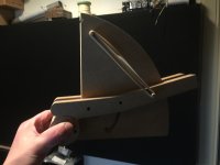
Oke i woke up this morning got to work and sat in the train...reread some of my posts,,, and this might be the best post of a contraption drawn in a 2d picture with text to explain what i try to do and. THERE IS NO WAY anyone going to understand it haha i had to be drunk when i wrote this (well i know i was) so i will mill some prototype maybe that explains a bit more. still sober(kind of) so There we go to the cold shed
here is the tool path of the contraption
haha i had to be drunk when i wrote this (well i know i was) so i will mill some prototype maybe that explains a bit more. still sober(kind of) so There we go to the cold shedhere is the tool path of the contraption
Attachments

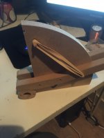
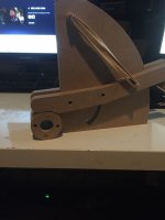
Well i finished the milling before i left home, and now took some pictures. hopefully this explains more
still managed to **** up making the tool path. first of all somehow the circles inner dimensions is not 22.3 mm but 21.7 so it wont fit on the metal pipe. further, one drill hole that is used as pivot for the clamp got misplaced in the tool path program (cambam) so it wont fit but both are easy to correct and should not be a problem in the future.
the clamping force with 1 rubber band on each side is pretty high thats good news i will add foam or rubber glue on the clams to increase friction so stuff wont creep.
still managed to **** up making the tool path. first of all somehow the circles inner dimensions is not 22.3 mm but 21.7 so it wont fit on the metal pipe. further, one drill hole that is used as pivot for the clamp got misplaced in the tool path program (cambam) so it wont fit
but both are easy to correct and should not be a problem in the future.the clamping force with 1 rubber band on each side is pretty high thats good news
i will add foam or rubber glue on the clams to increase friction so stuff wont creep.Attachments
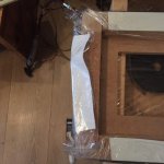
Ok i gave the tire contraption one more go..
But i had a nother problem, which it thought i fixed.... i tape the mylar with double sided tape on the bottom of the jigg. i noticed creep of the tape and even complete failure. now i added adhesive on the wood, so the tape wont slip as much. but in my latest test this was the result the next morning. so complete failure at some parts and minor on others.
It only takes a very very small creep or loosening of the tape to screw up my test results.
I tested on this same jigg with the same tape a :
1. Normal stretched Mylar.
2. Heated Mylar then stretched.
It gave some nice results. BUT since this morning i discovered this tape being as it is..... both tests are compromised. the lowering of the resonance could well be the tape sliding ever so slightly.
before i make this weird looking jigg i want to give this more simple method one more change.
Whats next! i will make a piece of wood that fits the bottom of this jigg, butis slightly wider. then the wood that holds the tape now. i will add the glue again to give it some more friction and then i will be using 32 clamps to hold the mylar stuck to the wood. i used these clamps once the same way as the original stretch jigg from quad they will hold on to the mylar no mater what, it will break before the clamp will let go.
If this still drops res frequency, its either the tire losing air, or the mylar overstretching.
i got high hopes. its a cheap and simple method of seeing whose to blame! for now its the tape and maybe something else. lets rule one out !
Attachments
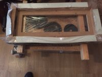
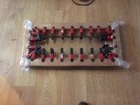
So , altered the frame to accept the clamps on the inner rim.
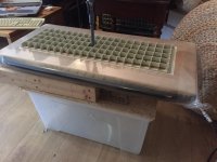
picture 1 i put Mylar on the floor and put the jig on top of it, wrap the mylar around at all sides, and use clamps to hold it in place. i might need a few more, if i can find some. another 12 or so will be more then enough.
picture 2 is the Mylar stretched with the measure mic on top of a stator. i look for the desired resonance in this case just a random high value and get my timer going to remeasure after 10,20,30 minutes then 1 hour etc. to see how much it drops.
Attachments
Last edited:
there on the translucent box, there is a wooden baffle with a woofer in it. i play a sweep from 20 to 120 hz, when swept there will be a peak of the resonance of the foil. the mc is really close to this foil so it will detect it easy as a big hump. in the frequency measurement
i like this method more then pulling on tape and such. since in this case it does not matter witch material you use(3 um 6 um 12 um), you measure what the resonance is of that particular membrane
almost forgot to mention the hole in the jig has the size of an quad panels foil area(without spacers), otherwise this would not be accurate.
Last edited:
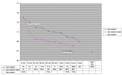
Did some testing with stretching mylar 3 um and 6 Um heated and not
i must admit for the 6 um stretch i used another inner tube. i wanted to use it on the 3 um but i ran out of 3um Mylar 40 meters gone without even fixing one ESL i am persistent to have it correctly working , i already ordered new mylar just 3 stretches before i ran out so when it arives i use it with the same tire once more. but still there are some funny things happening
by the looks of it the 6 Ûm is most stable. but since i changed inner tube i still have to do it once more with the 3Um oh god. (might have been the tube at fault , that would be a waste)
Another thing to notice that the heated foil drops quickly and then setles in compared to the ongoing unheated 3 um foil witch keeps dropping.
One thing i can say about the test is that it shows that my clamps are holding, at least. so next up to rule out is the inner tube.
i must admit for the 6 um stretch i used another inner tube. i wanted to use it on the 3 um but i ran out of 3um Mylar
40 meters gone without even fixing one ESL i am persistent to have it correctly working , i already ordered new mylar just 3 stretches before i ran out so when it arives i use it with the same tire once more. but still there are some funny things happeningby the looks of it the 6 Ûm is most stable. but since i changed inner tube i still have to do it once more with the 3Um
oh god. (might have been the tube at fault , that would be a waste)Another thing to notice that the heated foil drops quickly and then setles in compared to the ongoing unheated 3 um foil witch keeps dropping.
One thing i can say about the test is that it shows that my clamps are holding, at least. so next up to rule out is the inner tube.
Attachments
Last edited:
Like to follow your diagram over a timespan of at least a month..
I´ll be waiting...
How do you measure the tension/relaxation?
would be nice but ...... i cant wait a month.
i measure it with a mic on top of the stretch jig and a hole the size of my quad panel in the jig, with a loudspeaker underneath. i use holmimpulse to sweep and see where the peak is.
so far when i stretched the mylar to a health 93 hz before i used the heat gun.(with 6um mylar thats pretty doable)
Then i heat the 6 um mylar especially where the tire stretch it. i heat it until the inner tube does not grow in size anymore, thats the maximum the mylar will stretch with this heat and tension. and then do some passes over the top.
now the res drops considerably straight down to 67 hz. and now for a change i wont correct it to the 74 hz like the rest. because i am wondering if the last action need to be the heating. in the quad jig it get the same tension all over the proces even in the oven it gets stretched. what i and many others do is just stretch or what i did so far stretch heat stretch to correct resonance.
there might be a difference in where the mylar will settle after it stretched with heat and where it will settle after heat + mechanical stretching.
i am not sure yet if i explain this correctly. i am just noticing that with this instance i dont seee the huge drop that all panels have common in the early 20 minutes.
beep beep beeeeeeeeeeeeeeeeeeeeeeeeeeeeeeeeeeeeeeeeeeeeeeeeeeeeep
................................beep beep.
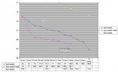
Well there is your flatliner. although something weird happens after 17 hours it seem to come alive. it did not drop but increases resonance haha not think this is a trend that continues to be honest but i leave it on the jigg to get some more data about the rise.
So stretch then heat. pretty solid outcome. at least more solid then stretching 6 um alone. but stretching heating and then stretch the last 10 hz does not work.
when i got some more data about the rising , i will try a this:
Stretch
Heat
measure
Stretch
Heat
measure
until i get the resonance i want. (prob when the foil does not want to stretch more with the heat.)
I test this because this is the only way to do it with 3Um foil.
Since 3um will break when stretched to 95 hz before you heat it, it cant stand it, max is around 74-78hz.
And i dont want to waste another 40 meter of Mylar , so i will be stretching it to around 65 then heat etc, and go to 70 hz in small steps.
................................beep beep.
Well there is your flatliner. although something weird happens after 17 hours it seem to come alive. it did not drop but increases resonance
haha not think this is a trend that continues to be honest but i leave it on the jigg to get some more data about the rise. So stretch then heat. pretty solid outcome. at least more solid then stretching 6 um alone. but stretching heating and then stretch the last 10 hz does not work.
when i got some more data about the rising , i will try a this:
Stretch
Heat
measure
Stretch
Heat
measure
until i get the resonance i want. (prob when the foil does not want to stretch more with the heat.)
I test this because this is the only way to do it with 3Um foil.
Since 3um will break when stretched to 95 hz before you heat it, it cant stand it, max is around 74-78hz.
And i dont want to waste another 40 meter of Mylar , so i will be stretching it to around 65 then heat etc, and go to 70 hz in small steps.
Attachments
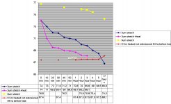
Ok 2 hours later. it looks like the rise was a faulty measurement. after 2 hours it it was back to 67.4.
So far i gained knowledge that my clamps are holding and my tire is not leaking any air. (not even a tiny bit) at least the panel would be glued by now. since glue dries in 40 to 60 minutes.
last be not least. you can see that just mechanical stretching a membrane then glue it to a stator is not gone give you a steady result. it will drop. be it 2.5 hz over 17 hours, who knows where it will end up
ESL63 wanted to know measurement over a time span of a month. and i am curious to. be it i cant miss my jigg for a month. or i have to buy new clamps.
another issue might be that a inner tube will lose some air over a month i bet!, so result will be slightly skewed. but on the other hand you can see the drop of the not heated membrane versus the heated quite clearly. so there will be a usable result with a small error margin.
conclusion thus far: if you design a ESL with a preferred resonance you cant just stretch it up and see what happens. this might only work if you know at wich resonance it will settle over time. this will cost you a long time figuring out, since there is no rule of thumb to the relaxation of the foil. it might not be linear at all.
Attachments

Last edited:
- Status
- This old topic is closed. If you want to reopen this topic, contact a moderator using the "Report Post" button.
- Home
- Loudspeakers
- Planars & Exotics
- My take on a stretch jig