A ribbon dipole tweeter reduced to the bare essentials that works and measures surprisingly well.
This is my third attempt at building a dipole ribbon tweeter, the first two used steel frames for holding the magnets and closing the field. This time I decided to drop the steel frame in an attempt to reduce the width of the tweeter as much as possible.
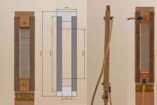
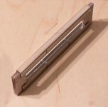
Dimensions are in millimeters. Thickness is just 9mm. What looks like single magnets are actually two custom N52 4mmx10mmx40mm magnets glued on a 1mm thick frame of aircraft quality plywood.
Using two magnets separated by a non-magnetic material results in a much more even flux density across the gap.
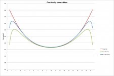
FEMM was used to simulate the flux density across a 19mm wide ribbon in a 20mm gap. The red line represents a single N40 (standard) magnet, the blue line represents dual N52 magnets with a distance of 0.5mm and the green line represents dual N52 magnets with 1mm distance. With the single magnet the maximum is much higher and located on the outermost edge, if you wanted to flex the ribbon this would be ideal. With the green line the difference between maximum and minimum is much less and the maximum is also located about 1mm from the edge, less corrugation will be required to prevent flexing of the ribbon.
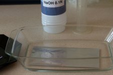
The ribbon itself is made from 10µm household aluminium foil etched down to about 5µm using a diluted sodium hydroxide solution.
The foil is cut to size using a roller cutter and corrugated with this simple contraption
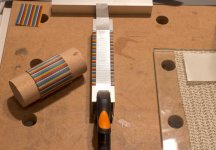
It’s even called ribbon cable Duh. The trick is to have just the right amount of corrugation, too little and there will be serious distortion, too much and you’ll get resonance problems.
How to drive this ribbon? Normally a transformer is used with this kind of (small) ribbon, I decided to try the brute force method with a series resistor and lots of power to see if this could work.
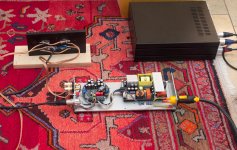
A Hypex NCore400 and four 0.5Ω 100W Caddock resistors. Not what you’d call an efficient approach but there are some advantages.
- The amp sees a nearly perfect resistive 2Ω load.
- Small variations in the contact resistance at the ribbon do not matter.
- Thermal compression is not an issue as the resistance and thus current is determined solely by the resistors.
So, how bad is it? Is it a space heater? No, it is not a space heater. Well, it will be if all you do is playing test tones at full power but with music the temperature of the heatsink barely rises above room temperature. Playing music very loud I measured peaks of 15A but the average was just over 3A.
Is it really a dipole? If so, up to which frequency? Next up, the measurements.
This is my third attempt at building a dipole ribbon tweeter, the first two used steel frames for holding the magnets and closing the field. This time I decided to drop the steel frame in an attempt to reduce the width of the tweeter as much as possible.

Dimensions are in millimeters. Thickness is just 9mm. What looks like single magnets are actually two custom N52 4mmx10mmx40mm magnets glued on a 1mm thick frame of aircraft quality plywood.

Using two magnets separated by a non-magnetic material results in a much more even flux density across the gap.

FEMM was used to simulate the flux density across a 19mm wide ribbon in a 20mm gap. The red line represents a single N40 (standard) magnet, the blue line represents dual N52 magnets with a distance of 0.5mm and the green line represents dual N52 magnets with 1mm distance. With the single magnet the maximum is much higher and located on the outermost edge, if you wanted to flex the ribbon this would be ideal. With the green line the difference between maximum and minimum is much less and the maximum is also located about 1mm from the edge, less corrugation will be required to prevent flexing of the ribbon.
The ribbon itself is made from 10µm household aluminium foil etched down to about 5µm using a diluted sodium hydroxide solution.

The foil is cut to size using a roller cutter and corrugated with this simple contraption

It’s even called ribbon cable Duh. The trick is to have just the right amount of corrugation, too little and there will be serious distortion, too much and you’ll get resonance problems.
How to drive this ribbon? Normally a transformer is used with this kind of (small) ribbon, I decided to try the brute force method with a series resistor and lots of power to see if this could work.

A Hypex NCore400 and four 0.5Ω 100W Caddock resistors. Not what you’d call an efficient approach but there are some advantages.
- The amp sees a nearly perfect resistive 2Ω load.
- Small variations in the contact resistance at the ribbon do not matter.
- Thermal compression is not an issue as the resistance and thus current is determined solely by the resistors.
So, how bad is it? Is it a space heater? No, it is not a space heater. Well, it will be if all you do is playing test tones at full power but with music the temperature of the heatsink barely rises above room temperature. Playing music very loud I measured peaks of 15A but the average was just over 3A.
Is it really a dipole? If so, up to which frequency? Next up, the measurements.
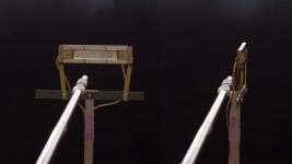
All measurements were performed using a Clio FW system and an MBNM 550 EL microphone. The level was calibrated with an ISO-Tech SLC 1356 sound level calibrator so the dBSPL numbers actually mean something. To prevent reflections the stand beam has an XLR connector glued into the tube. Here’s a picture showing the setup for measuring vertical directivity.
In the following graphs the measurement parameters are always displayed below the graph. All frequency response measurements, directivity graphs and cumulative spectral decay plots are unsmoothed!
Let’s start with the frequency response measured at a distance of 50cm, vertically centered.
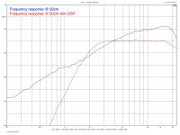
The vertical scale is 50dB. The blue line shows the response for the unfiltered ribbon. As you can see by the 6dB/oct slope it is actually a dipole, I would say up to about 7kHz. The red line shows the response for the driver with DSP applied. A Hypex DLCP was used with the following settings:
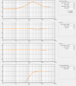
Just for biquads are required. There is a slight drop-off above 16kHz but -2dB at 20kHz is good enough for me, that’s the price one has to pay when using a ribbon that is 19mm wide. I wonder if the little blip above 7kHz is actually the dipole peak, this would make it a candidate for EQ correction. If that blip is removed the response is flat within 0.5dB from 3kHz to 16kHz, not bad, not bad at all.
Here is the cumulative spectral decay for the ribbon with DSP:
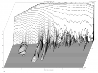
The vertical scale is 40dB, the time window is 5ms. All in all a very quick and clean decay. My theory is that the mass of the ribbon is so low (with respect to the surface area) that the surrounding air provides the necessary damping, remember that because of the series resistor there will be no electrical damping to speak of.
Next up are the directivity measurements.

In the following graphs the measurement parameters are always displayed below the graph. All frequency response measurements, directivity graphs and cumulative spectral decay plots are unsmoothed!
Let’s start with the frequency response measured at a distance of 50cm, vertically centered.

The vertical scale is 50dB. The blue line shows the response for the unfiltered ribbon. As you can see by the 6dB/oct slope it is actually a dipole, I would say up to about 7kHz. The red line shows the response for the driver with DSP applied. A Hypex DLCP was used with the following settings:

Just for biquads are required. There is a slight drop-off above 16kHz but -2dB at 20kHz is good enough for me, that’s the price one has to pay when using a ribbon that is 19mm wide. I wonder if the little blip above 7kHz is actually the dipole peak, this would make it a candidate for EQ correction. If that blip is removed the response is flat within 0.5dB from 3kHz to 16kHz, not bad, not bad at all.
Here is the cumulative spectral decay for the ribbon with DSP:

The vertical scale is 40dB, the time window is 5ms. All in all a very quick and clean decay. My theory is that the mass of the ribbon is so low (with respect to the surface area) that the surrounding air provides the necessary damping, remember that because of the series resistor there will be no electrical damping to speak of.
Next up are the directivity measurements.
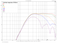
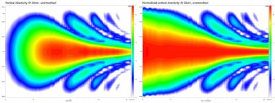
I measured the directivity in 5 degree steps from 0 to 90 degrees, the plots are mirrored to create a 180 degree plot. Let’s start with the bad news, the vertical directivity. The vertical directivity is, of course, the weakness of a ribbon driver. The question is whether it is acceptable for the intended purpose.
Vertical response for several angles:
Directivity and normalised directivity:
Normalised polar plots:
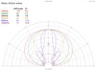
At 8000Hz the -6dB angle is just 30 degrees, at 16kHz it’s not even 20. There is serious beaming but it’s not too bad and at least it’s pretty much textbook behaviour. The lobing is below -12dB, everything above is very smooth. The main consequence is that there is a minimum listening distance of about 3m, this clearly rules out any application in a near-field monitor but the ribbon certainly can be used in a larger multi-way system.
And now for the piece the resistance, the horizontal directivity.
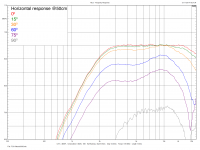
The response for several angles:
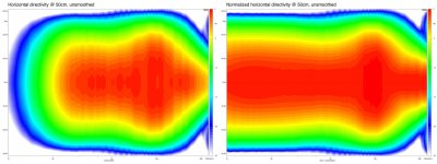
Directivity and normalised directivity
Normalised polar plots:
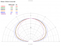
Pretty much constant directivity up to about 7kHz, there’s a little widening around 10kHz and narrowing above that. I think you’ll be hard pressed to find anything that’s better than this.
The last item on the measurement list is the harmonic distortion. The distortion was measured ‘in situ’ together with a B&G Neo10 magneplanar. The scale for the fundamental is in dBSPL on the left, the scale for the harmonics is linear in % on the right with 1% full scale.
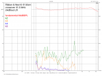
The 2nd harmonic has a peak of 0.44% just below 7kHz but for the most part stays below 0.3%. The 3rd has a bit of a plateau of 0.2% from 1.5kHz to just above 3kHz. The higher harmonics start out at 0.1%, which is definitely on the high side but fortunately they drop to 0.02% at 3kHz.
There is room for improvement here and this will be the subject of further study.
On a practical note, this ribbon is very insensitive to draft which is very nice. Nevertheless it’s wise to keep a set of spares handy just in case:
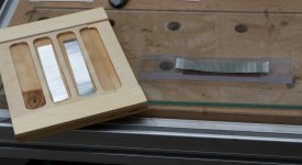
Although this open construction is inherently vulnerable the fact you can fit a new ribbon in under 15minutes removes most of the worries. There is also no need to worry about amplifier failure. There are only low cost and readily available materials involved in the making of the ribbon itself so it’s no problem the make a couple more.
regards,
Gerrit
Vertical response for several angles:

Directivity and normalised directivity:

Normalised polar plots:

At 8000Hz the -6dB angle is just 30 degrees, at 16kHz it’s not even 20. There is serious beaming but it’s not too bad and at least it’s pretty much textbook behaviour. The lobing is below -12dB, everything above is very smooth. The main consequence is that there is a minimum listening distance of about 3m, this clearly rules out any application in a near-field monitor but the ribbon certainly can be used in a larger multi-way system.
And now for the piece the resistance, the horizontal directivity.
The response for several angles:

Directivity and normalised directivity

Normalised polar plots:

Pretty much constant directivity up to about 7kHz, there’s a little widening around 10kHz and narrowing above that. I think you’ll be hard pressed to find anything that’s better than this.
The last item on the measurement list is the harmonic distortion. The distortion was measured ‘in situ’ together with a B&G Neo10 magneplanar. The scale for the fundamental is in dBSPL on the left, the scale for the harmonics is linear in % on the right with 1% full scale.

The 2nd harmonic has a peak of 0.44% just below 7kHz but for the most part stays below 0.3%. The 3rd has a bit of a plateau of 0.2% from 1.5kHz to just above 3kHz. The higher harmonics start out at 0.1%, which is definitely on the high side but fortunately they drop to 0.02% at 3kHz.
There is room for improvement here and this will be the subject of further study.
On a practical note, this ribbon is very insensitive to draft which is very nice. Nevertheless it’s wise to keep a set of spares handy just in case:

Although this open construction is inherently vulnerable the fact you can fit a new ribbon in under 15minutes removes most of the worries. There is also no need to worry about amplifier failure. There are only low cost and readily available materials involved in the making of the ribbon itself so it’s no problem the make a couple more.
regards,
Gerrit
You're welcomeI like your solution for applying corrugation to the ribbon. That was always a snag for me when I built ribbons.
Thanks for sharing your project.
John
I too have had problems (mainly getting perfectly straight ribbons) until I came up with this simple method. I've tried several different ribbon cables:
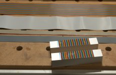
The coloured one worked best for me. I'm still experimenting with this to try to further reduce distortion without introducing resonances.
regards,
Gerrit
ThanksTerrific!
Dave.
Here's a picture of another one on top of a Neo10 magneplanar.
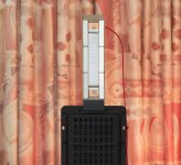
The contact blocks and clamp are made of plastic, don't know what exactly but it can withstand acetone. Copper foil from a foil inductor is glued to the block that is fixed in the frame. You can see it through the block that acts a clamp. For easy positioning of the ribbon I use VanDenHul 'The Solution' contact fluid. This stuff is a bit viscous, like maple sirup, and makes it very easy to align the ribbon in the gap.
regards,
Gerrit
Very nice Build and Impressive Charts !!!!
jer
Thank you
Another picture, the clamping blocks in detail:
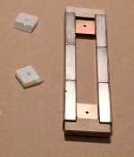
The protective foil is still on the clamps. The hole in the contact blocks is threaded M3. The contact blocks are electrically isolated from the magnets by 0.3mm thick pertinax strips.
regards,
Gerrit
I like this very much, even I could build it. But, can You show the magnetic poles orientation (N/S or E/W) just to make it clear to me....
Here's the drawing I used to explain it to the people where I ordered them:
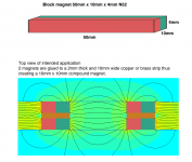
Beware that these are custom magnets so there is a minimum order quantity.
Some more pictures of the construction:
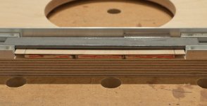
Here you see the 7th magnet glued in place. I used a piece of 20mm wide steel strip to align the magnets. The first six magnets are relatively easy to fix, the next six are more difficult. If you're not careful the magnets will slip from your fingers, flip around, and align themselves the wrong way.
Here's a picture of magnet number 8 clamped in place:
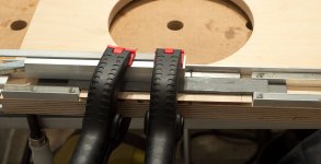
You have to really push it against the magnet already glued in place. With all magnets glued in place additional pieces of plywood are are glued at the ends:
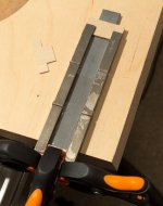
I used 1mm plywood mainly because I had it lying around, of course you can also use other materials.
regards,
Gerrit
You write that the magnets are custom. Where can one source such magnets? Looks like a fun build!
I ordered them at NEOTEXX but any shop that does custom work should be able to provide them. The minimum order quantity for custom magnets at Neotexx is €200,- so that's a bummer but it will get you 100 magnets.
My previous design uses a steel plate to close the field, this will result in a stronger field and you can use standard magnets:
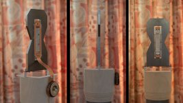
This is not a true dipole but it still works pretty well, I use these for my surround speakers. I plan to make an improved version with dual magnets and a slightly smaller frame:
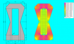
regards,
Gerrit
You write that the magnets are custom. Where can one source such magnets?
Here are some regularly stocked magnets I've used for ribbon projects in the past.
They aren't the exact dimension used for this project, but they are magnetized in the desired direction for the construction configuration.
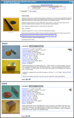
cPath_5 | products_id_360 | Neodymium Magnets N42 Long Bar 3 in x 1/8 in x 5/16 in - Applied Magnets & WindMax Wind Turbines
K&J Magnetics: BX024
K&J Magnetics: BX028
Attachments
What do You mean it's not a dipole? As I can see from the photo, it is opened on both sides (front and rear) to radiate in true dipole,or I missunderstood something...
It may be a matter of semantics but in my book a true dipole will have a 6dB/oct slope in the response due to the cancellation of the front wave by the back wave. The steel frame is too wide for that, there is no slope in the response and the polar response isn't as good.
Although the 6dB/oct slope requires serious equalisation I it's worth it because of the excellent directivity. The fact that the ribbon has prefect symmetry and excellent directivity results in a very sharp and stable stereo image, much better than the Linkwitz Orion's I had before this system.
Because the ribbon without the steel frame is smaller it can be placed closer to the mid driver which is also beneficial.
regards,
Gerrit
Hi Gerrit,
Nice work, i you play al little with the tension of the ribbon you can lose or flatten the distortion peak.
I always use weight to get the same tension.
Rob
Thanks
I was planning to do just that, experimenting with the tension. Don't know if a using weight would work with my design, there is very little room, but I'll keep it in mind. I was thinking of adapting my corrugation contraption so that a fixed length can be corrugated, a bit shorter than the gap height, so I can get the right tension by stretching the ribbon until the corrugation touches the clamps.
As far as the frequency response is concerned the repeatability is excellent:
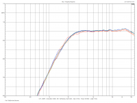
The graph shows the response for six different ribbons, the red and orange lines are for slightly thicker ribbons (6µm vs 4.6µm).
regards,
Gerrit
ThanksVery nice work, very well documented! I'm late to this party but wanted to say thanks for sharing your experiences. It's helpful to those of us following related paths.
Few
That was the main reason for sharing this, so that other people might find some useful information for their own projects or perhaps even build this simple design.
One thing I would like to try is to see if it is possible to create a cardioid by applying damping to the back. This would have the advantage of a constant directivity without the dipole losses.
regards,
Gerrit
- Home
- Loudspeakers
- Planars & Exotics
- DIY ribbon dipole tweeter, reductio ad minimum
