I mean literally , stator on stator on stator on stator :0
i made a small sandwich of a tiny panel for tweeter use, to see if this could work and to see what happens.
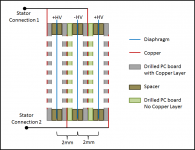
i costructed it so that all solder terminals are on the rim the high voltage terminals are tunrded 180 degree every stack so left is +HV right -Hv. etc
the panel is round and better would be a bit more oval, to get rid of some weird peaks and control vertical dispersion.
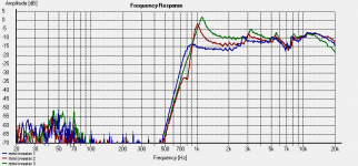
i measured first one solo panel (as you can see there are already some weird peaks, not sure what it is might be the fact its round) then i added one layer of insulation, a stator without copper but with all the holes as a normal stator. then a spacer with High voltage connection and another stator with spacer and menbrame.
since i dont swap stator polartity i switch polarity of the menbrame . i got one Hv + and one HV -, after each stacking i did a measurement to see what happens.
you can see that it almost ignores high frequencys, there is no gain. but the lower you go it does add up. and what is cool it composates for the roll off it had on the single panel.
second thing noticed clearly and we allready knew ofcourse, is resonance goes up.
Im looking forward to make a tiny bigger one with a little more room for the menbrame, with 0.5 mm spacing its pretty hard to keep the foil out of the stator. and lower the resonance. i would adopt the same design increase spacing a bit to 0.8 and add 2 more rings to it to lower res and play lower.
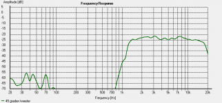
The high frequencys are pretty nice look at the dispersion, i think its rather ok. i cant hear any difference when i move my head. would be nice to make it a little bit higer then its wide, to not scatter high frequencies around the room where its not needed. vertical dispersion controll") i measured all dispersion from approx 1 meter distance and smoothed 1/6th
i measured all dispersion from approx 1 meter distance and smoothed 1/6th
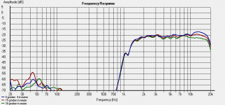
i dont have a graph of the 4th stack, but its the same as the 2 and 3rd stack with some more SPL in the lower end and higher res freq. 1100hz.
the high frequency response of the 3rd stack is actually almost the same as second stack, dont know what i did wrong when i measured that. the opveral rolloff at 20k might be my class D amp, i will try to connect it to my main amplifier
i chose the size of the middle part based on a big tweeter, 1 inch +- 25 mm
i made a small sandwich of a tiny panel for tweeter use, to see if this could work and to see what happens.
i costructed it so that all solder terminals are on the rim the high voltage terminals are tunrded 180 degree every stack so left is +HV right -Hv. etc
the panel is round and better would be a bit more oval, to get rid of some weird peaks and control vertical dispersion.
i measured first one solo panel (as you can see there are already some weird peaks, not sure what it is might be the fact its round) then i added one layer of insulation, a stator without copper but with all the holes as a normal stator. then a spacer with High voltage connection and another stator with spacer and menbrame.
since i dont swap stator polartity i switch polarity of the menbrame . i got one Hv + and one HV -, after each stacking i did a measurement to see what happens.
you can see that it almost ignores high frequencys, there is no gain. but the lower you go it does add up. and what is cool it composates for the roll off it had on the single panel.
second thing noticed clearly and we allready knew ofcourse, is resonance goes up.
Im looking forward to make a tiny bigger one with a little more room for the menbrame, with 0.5 mm spacing its pretty hard to keep the foil out of the stator. and lower the resonance. i would adopt the same design increase spacing a bit to 0.8 and add 2 more rings to it to lower res and play lower.
The high frequencys are pretty nice look at the dispersion, i think its rather ok. i cant hear any difference when i move my head. would be nice to make it a little bit higer then its wide, to not scatter high frequencies around the room where its not needed. vertical dispersion controll
i measured all dispersion from approx 1 meter distance and smoothed 1/6thi dont have a graph of the 4th stack, but its the same as the 2 and 3rd stack with some more SPL in the lower end and higher res freq. 1100hz.
the high frequency response of the 3rd stack is actually almost the same as second stack, dont know what i did wrong when i measured that. the opveral rolloff at 20k might be my class D amp, i will try to connect it to my main amplifier
i chose the size of the middle part based on a big tweeter, 1 inch +- 25 mm
Attachments
Last edited:
im listening to them mates with a 12 inch OB, and im pretty impressed. crossed at 1450Hz bit higher then i would like, but still it sounds pretty good, and the dispersion is .... well i love to not be bound to one spot! , i sit in another room while i type this and i can hear everything clearly , also the highs. i ordered another batch of 0.5 mm pcb i have to play with this a bit more im affraid. i also tried my clas AB amp and the roll of at 18Khz is not my class D, maybe its the transformer, since the solo panel has the same roll off. either on class D or AB
i have to play with this a bit more im affraid. i also tried my clas AB amp and the roll of at 18Khz is not my class D, maybe its the transformer, since the solo panel has the same roll off. either on class D or ABwelll believe it or not i have made the thing, where i usually think what does it add. a video. since my iphone sucks ofcourse. but it does give you a slight idea about dispersion. although i sometimes do watch these video's when im interested in some sort of design. but ofcourse you cant judge a speaker on it. also funny is i can hear my room (acoustics) really good on the phone its not dead thats for sure. pardon me for being wobbly, i might had a beer to much during listening
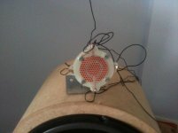
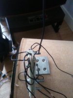
here is the monstrosity
https://www.youtube.com/watch?v=RBOjg3MTKa4
when i stand up you can really hear the room acoustics being twice as loud. funny because i did not notice this when i did it.
One thing to notice , The solo panel is almost 10 dB down in the lower frequency compared to the triple layered. compared to the 4 layer its even more like 12
its not dead thats for sure. pardon me for being wobbly, i might had a beer to much during listening here is the monstrosity
https://www.youtube.com/watch?v=RBOjg3MTKa4
when i stand up you can really hear the room acoustics being twice as loud. funny because i did not notice this when i did it.
One thing to notice , The solo panel is almost 10 dB down in the lower frequency compared to the triple layered. compared to the 4 layer its even more like 12
Last edited:
Wow............that's just one speaker...........I like what I hear....phone is not bad at all...........I have heard a lot of speakers on youtube that I have owned an its a shock how close there sound is to my ears............to the sound in my room......I say your sound on ......1-10.......8....thanks
Hi,
stacking two is fine. It can give You up to +6dB of SPL at lower frequencies.
That may be just enough to cancel the acoustic phase cancellation, thereby lowering the demand for electronic EQ and drive power.
The effect lowers with rising frequency and from the upper midrange on there's no benefit anymore but phase issues begin, depending on the distance of the diaphragms.
With a design of n diaphragms and n+1 stators, phase issues up to total cancellation are inherent as it is impossible to achieve less than a few mm of membranes distance.
jauu
Calvin
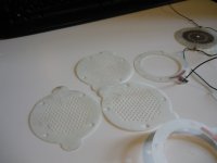
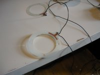
here are some pictures of the seperate parts. they are all sandwiched with 4 bolts. i added a white tiny dot as membrane support in the middle, not yet tested. might raise the res to high to be of any use. test will tell.
Pic 1 A spacer with Hv connection
Pic 2 3 stators with spacer and the membrane
Pic 3 Isolation stator, it is the same as a stator except without copper, to put on the copper side of a stator, so the actually copper to membrame distance is +-1 mm between every stator (0.5 air, 0.5 mm pcb material then the copper on that pcb)
Pic 4 other isolators.
as calvin mentioned and as i showed in the graph its usefullness is to counter eq in lower frequencies. i think thats verry interesting, when you want small size panels. th small sanwich here could even fit in a dustcap of a 15 inch to make a point source. it has a 87 mm in diameter in total (with the little ears) it wont fit into a coil former
in the graph you can see the gain starts to be usefull from 3 khz and down.
Attachments
Last edited:
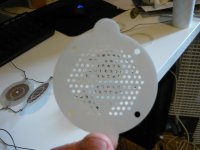
Well the dot keeps the menbrame out of the stators, i can up the high voltage until one of my caps start emiting light... they are not rated for that voltage thats for sure. i forgot that as long as the ac you fed the cascade the caps dont have to be higher value then the ac voltage aplied at the start. since i feed them with an inverter that can easy put out 900 volt i ran into the limits of the caps. might need bigger caps or make the cascade longer so i dont have to put in such high voltage. but that aside. this is what the dot does.
1 it keeps mylar out of stator
2 raises res freq for a 3 sandwich panel from 1100 to almost 1380hz
3 i lose out on high feq since the place where the dot is cant move forward or backward, it has less radiating area now. normally in a large panel that tiny dot wont make a difference in output, but since this panel is so small the dot is like 1/8 of the total emitting surface for the high frequency. (the circle in the middle)
So next time i should try not to put the dot in the area of the high frequency, since stacking does boost the lower freq but not the highest, so losing out on that because of a support dot is not a good idea. also placing the dot asymetrical would be better for resonances. although when i see a circle i really want to put it in the middle i love symmetry
1 it keeps mylar out of stator
2 raises res freq for a 3 sandwich panel from 1100 to almost 1380hz
3 i lose out on high feq since the place where the dot is cant move forward or backward, it has less radiating area now. normally in a large panel that tiny dot wont make a difference in output, but since this panel is so small the dot is like 1/8 of the total emitting surface for the high frequency. (the circle in the middle)
So next time i should try not to put the dot in the area of the high frequency, since stacking does boost the lower freq but not the highest, so losing out on that because of a support dot is not a good idea. also placing the dot asymetrical would be better for resonances. although when i see a circle i really want to put it in the middle
i love symmetryBungard.nl produktoverzicht
And another one , but i don't have the adres at hand , will let you know when I'm home
And another one , but i don't have the adres at hand , will let you know when I'm home
Hi,
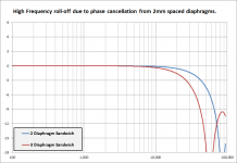
the first graph in #1 shows differences in HF amplitude response above 12kHz, with sinking SPL for increasing Diaphragm number count.
This is as expected due to phase cancellation.
Remember that 180° phase shift at 20kHz equals 8.5mm distance.
On second thought ... You mentioned using a class-D amp for measurement.
Especially if that is a pre-filter-feedback design it will react strongly on the attached capacitance with a HF peak.
For reliable and repeatable measurements You should use a decent linear amp.
Class-D rules out for this purpose..
jauu
Calvin
I hear prefilterfeedback HF peaking with dynamic speaker/rising impedance. I don't hear HF peaking with electrostatic/dropping impedance. Does ofcourse not mean it doesn't happen, interesting remark, interested in reason why prefilterfeedback class d would peak with capacitive load.
I measured on a AB amp as well, plots are exactly the same. i thought just as you that the filter might screw with the results, but it aint.
Further its funny 2 panels stacked has more high frequency response then 1 sothat seem to be the limit on the high frequencys. but!
what i can do is let the first 2 stacks play fulrange in the middle, then the other stacks i filter the same as the outer ring, so without the the highest fequencys. (or at least under 12k)
i wil end up if im correct, with no phase cancelation. since the added stacks influency the lower frequency more i still benefit from adding stacks. the more stackes the more i need to filter to keep out of the 180 phase shift
Ok i tried filtering the 2 and 3rd stack of a 4 stacked version. SPL in high freq drops even harder. best result was 3 stacked esl where i filtered the rear stack to not emit high fequencys .
Calvin you mentioned 8.5mm for 20Khz 180 degree phase shift. i just thought about my panels, they are 2 mm thick, so 4 panels is the maximum, that can be used. 8 mm in total, but the membrames are ofcourse 2 times 0.5 mm closer to one another.
3 panels would be best.
i think there might be some gain in using thinner foil and even less DC spacing. SPL goes up and the amount of panels you can stack goes up as well without running into the 180 phase shift on 20Khz. i use 3 Mircron foil right now. any one have even thinner mylar ?
then again who hears 20Khz, a child might
you can see that it almost ignores high frequencys, there is no gain. but the lower you go it does add up. and what is cool it composates for the roll off it had on the single panel.
Interesting measurement trends for 1 vs 2 vs 3 diaphragms...
Can you describe the electrical components between the amplifier and the stators?
1) Did you have any series resistance between amplifier and step-up transformers?
2) Did you have an series resistance between the transformers and the stators?
The trends you see could be explained from series resistance.
At higher frequency the whole unit would be driven at constant current defined by the resistance(same SPL when more sections added), but transitioning to constant voltage at lower frequencies(increased SPL when more sections added).
Concerning Phase Cancellation due to Diaphragm Spacing:
If I understand your construction correctly, the diaphragms are spaced 2mm apart. Is Pic#1 correct?
If so, this would result in very little phase cancellation just as you measured.
Concerning Class D amplifier HF response:
It all depends on the exact amplifier and load impedance.
For an example of what can happen, see my measurements of a Behringer iNuke:
http://www.diyaudio.com/forums/class-d/213071-behringer-inuke-nu3000-measurements.html#post3031769
BTW you can get similar peaking behavior with Class A/B amps when driving ESLs, depending on their Zobel output network.
The only way to know what part of the response if coming from the amplifier is to measure the input voltage to the transformer primary while driving the ESLs.
Attachments
- Status
- This old topic is closed. If you want to reopen this topic, contact a moderator using the "Report Post" button.
- Home
- Loudspeakers
- Planars & Exotics
- sandwich esl ?Yummie