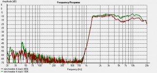
Interesting measurement trends for 1 vs 2 vs 3 diaphragms...
Can you describe the electrical components between the amplifier and the stators?
1) Did you have any series resistance between amplifier and step-up transformers?
2) Did you have an series resistance between the transformers and the stators?
The trends you see could be explained from series resistance.
At higher frequency the whole unit would be driven at constant current defined by the resistance(same SPL when more sections added), but transitioning to constant voltage at lower frequencies(increased SPL when more sections added).
Concerning Phase Cancellation due to Diaphragm Spacing:
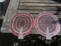
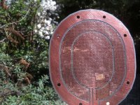
If I understand your construction correctly, the diaphragms are spaced 2mm apart. Is Pic#1 correct?
If so, this would result in very little phase cancellation just as you measured.
Concerning Class D amplifier HF response:
It all depends on the exact amplifier and load impedance.
For an example of what can happen, see my measurements of a Behringer iNuke:
http://www.diyaudio.com/forums/class-d/213071-behringer-inuke-nu3000-measurements.html#post3031769
BTW you can get similar peaking behavior with Class A/B amps when driving ESLs, depending on their Zobel output network.
The only way to know what part of the response if coming from the amplifier is to measure the input voltage to the transformer primary while driving the ESLs.
Nice picture Bols! (i wanted to make something like that to show what i was doing but was to lazy) this is exactly how i made them, and indeed 2 mm foil to foil. 0.5 mm stator +0.5 mm spacer + menbrame +0.5mm spacer +0.5 mm backstator
1) Did you have any series resistance between amplifier and step-up transformers?
Nope connected directly, crossover is with minidsp. i know use my Pioneers A757 ref Amplifier its class AB, before i used the TPA3166 , wich i will be using in the final product, as as active biamped loudspeaker. and i did not see the drop of high freq in my measurement i compared them directly and they are exactly the same. (still would be able that bth amplifiers are not flat, this i cant check or measure)
2) Did you have an series resistance between the transformers and the stators?
Yes only on the outer ring. i know (just like the fault i made with the ESLgui program) that capacitance doubled ofcourse when i stacked to 2 and from 2 to 4. i should decreased resistors. i did not
 there is a 400K resistor on that ring. this could explain the little drop on high frequency when adding panels. **** dont feel like getting them appart again for the 4th time today ill change the resistor to see if it takes on the same curve!
Nice picture of the the cancelation as well, all looking so pro
thanks. yeah so with 3 stacks it does start to roll off a little before 20 khz, but thats is not really a problem since there is this 6 db/oct increase when frequency rises. (less now since the stacking ofcourse ) I will measure them with a 100k resistor right now to see how the plot looks.
Last edited:
Quick measurement 400k and 100k serie resistor on outer ring for the same 4 stacked.
i should remove one stack tomorow 3 is the max with 2mm membrame spacing. as you can see the high falls of at 16 khz with or without 400k or 100k
i added a support dot to have the membrane not colapse into the stator, and it *** up a part of the high frequency response, and its hard to compare to the measurements from yesterday. might need to make some new ones and start all over (and change the resistors when adding stacks, in theory we know 3 is the max for this version.) i do have the feeling that i might use somethign like this. i like to make bigger size tweeter that plays from 600hz and up, would be awesome
with the 100 k serie resistor i got more output, but it also affect dispersion a bit, although when i move my head it is still no comparison with a normal small panel i can freelly move
By the way Bolsert what programs you used to make all those nice graphs?
i should remove one stack tomorow 3 is the max with 2mm membrame spacing. as you can see the high falls of at 16 khz with or without 400k or 100k
i added a support dot to have the membrane not colapse into the stator, and it *** up a part of the high frequency response, and its hard to compare to the measurements from yesterday. might need to make some new ones and start all over (and change the resistors when adding stacks, in theory we know 3 is the max for this version.)
i do have the feeling that i might use somethign like this. i like to make bigger size tweeter that plays from 600hz and up, would be awesomewith the 100 k serie resistor i got more output, but it also affect dispersion a bit, although when i move my head it is still no comparison with a normal small panel i can freelly move
By the way Bolsert what programs you used to make all those nice graphs?
Attachments
Last edited:
oh and one of those terible youtube iphone recordings with typical youtube iphone music (i do like regina spektor for real, by the way)
http://youtu.be/afl3lpRHSn0
(i do like regina spektor for real, by the way)http://youtu.be/afl3lpRHSn0
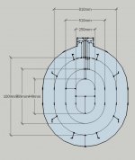
Well this is the next design, i made it vertically a little bit bigger to limit vertical dispersion (hope not to much) further more i added a ring to extend the low frequency's and as well lower the resonance.
The image shows the concept, scale 10:1 because sketchup does not cope well with 0. something mm so i scale it down in the program to convert to toolpaths for my cnc.
total surface area is 3 times that of the first prototype i made. i will only use 3 stacks max, as proven that that is the best compromise, in high frequency. furthermore i will let the cnc drill all the holes with a 2mm bit and let him take a way a bigger diameter of only copper to prevent arcing when high voltage is used. let say the hole is 2mm and i remove 2.5 mm so burs caused by drilling are not above the drill hole.
all dimensions need to be scaled down by 10. so the mid high frequency sigment is actually 25 mm wide.(same size as a big dome tweeter)
this time i made all connections of one stator on one side, this is nice when i put on the back stator turn the whole thing 180 degree so the connections end up on the bottom side. this is easy when i want to daisy chain the stators. top connections are Positive stator bot negative. same for the HV bias connections left will be +bias right -bias (this spacer is not drawn in this image)
i guess i get my PCB material in tomorow, but i wanted to get rid of all the copper for the spacers this time by Etching. instead of using the cnc to keep tolerances high. but the store that sells etching stuff it is not open tomorow i might go balistic on some house hold chemicals.
The image shows the concept, scale 10:1 because sketchup does not cope well with 0. something mm so i scale it down in the program to convert to toolpaths for my cnc.
total surface area is 3 times that of the first prototype i made. i will only use 3 stacks max, as proven that that is the best compromise, in high frequency. furthermore i will let the cnc drill all the holes with a 2mm bit and let him take a way a bigger diameter of only copper to prevent arcing when high voltage is used. let say the hole is 2mm and i remove 2.5 mm so burs caused by drilling are not above the drill hole.
all dimensions need to be scaled down by 10. so the mid high frequency sigment is actually 25 mm wide.(same size as a big dome tweeter)
this time i made all connections of one stator on one side, this is nice when i put on the back stator turn the whole thing 180 degree so the connections end up on the bottom side. this is easy when i want to daisy chain the stators. top connections are Positive stator bot negative. same for the HV bias connections left will be +bias right -bias (this spacer is not drawn in this image)
i guess i get my PCB material in tomorow, but i wanted to get rid of all the copper for the spacers this time by Etching. instead of using the cnc to keep tolerances high. but the store that sells etching stuff it is not open tomorow
i might go balistic on some house hold chemicals.Attachments
Last edited:
There ya goQuick measurement 400k and 100k series resistor on outer ring …

Always need to be aware of series resistance when plotting trends for added panel area or sections because of the increased capacitance.
Most of the plots I post are made in Excel.By the way Bolsert what programs you used to make all those nice graphs?
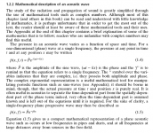
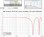
I find it really convenient to be able to quickly plot comparisons for any equations I might be interested in rather than searching for a piece of software that probably won't do things exactly like I want anyways. For example, the amplitude and phase for 1-D wave propagation for any distance from the source is a very simple formula(Eq 1.5). Using Excel, you can place diaphragms at different distances from each other and sum the resulting output.
Attached is the Excel spreadsheet I used to make the plot.
(You will need to have the Excel Analysis Tool Pak loaded/activated)
https://www.add-ins.com/Analysis_ToolPak.htm
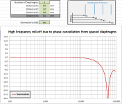
I had been considering similar point-source mid-tweeter multi-diaphragm arrays, so already had a spreadsheet created for 1 to 4 diaphragm.
As a test case, select 2 diaphragms and space them 8.5mm apart and you should get a null at 20kHz(as Calvin mentioned).
NOTE: this calculator only show contribution to response from phase cancellation of spaced diaphragms.
It does not consider anything else, like diaphragm mass, stator transparency, etc...
Attachments
Last edited:
There ya go
Always need to be aware of series resistance when plotting trends for added panel area or sections because of the increased capacitance.
Most of the plots I post are made in Excel.
I find it really convenient to be able to quickly plot comparisons for any equations I might be interested in rather than searching for a piece of software that probably won't do things exactly like I want anyways. For example, the amplitude and phase for 1-D wave propagation for any distance from the source is a very simple formula(Eq 1.5). Using Excel, you can place diaphragms at different distances from each other and sum the resulting output.
Attached is the Excel spreadsheet I used to make the plot.
(You will need to have the Excel Analysis Tool Pak loaded/activated)
https://www.add-ins.com/Analysis_ToolPak.htm
I had been considering similar point-source mid-tweeter multi-diaphragm arrays, so already had a spreadsheet created for 1 to 4 diaphragm.
As a test case, select 2 diaphragms and space them 8.5mm apart and you should get a null at 20kHz(as Calvin mentioned).
NOTE: this calculator only show contribution to response from phase cancellation of spaced diaphragms.
It does not consider anything else, like diaphragm mass, stator transparency, etc...
Oooh wow nice Bolsert, you are beter in mathematics then me thats for sure (EDIT you are a aerospace engineer, this could be my understatement of the year i guess
) i always failed at it in highschool and i still relly allot on "these software" i can spawn a good idea every now and then but always have to look up everything (in triple) and excel always has been a downfall for me i dont get anything excel hahalove to have ur excel sheet! since i need those things
haha. well its funny that i try building one and almost everyone has been thinking of one. i might be more of the hands on type, with all ****** allong the way. (usually more expensive to) but its a good combination. so im glad everyone is shining there light on the subject!about the subject open percentage and membrame weight i want to do some tests still. i might buy some 2 micron foil, although its only 1 micron lighter then i have now. and percentage of open area might be of bigger influence, this i can test without to much costs.
i get my material tomorow, i will make a complete set as described above, and since im always in a hurry i will finish it by the end of the day. i then (if there is time) wil also make 4 stators and 4 stator shields (this is what im gone call the blanc stators without copper from now on if thats ok) with a higher open area. see what the diference is. i can imagine it could help with the weird peaks im having even when close mic'ed.
cant wait until i got my pcb tomorow
and thx bolsert for the excel sheet verry much apreciated!!!
Last edited:
*.xlsx files ARE Excel files, but can only be opened by Excel 2007 or newer.Bolsert i cant open it , are you sure its Excel? says Xlsx, i am windows based not sure if it makes any difference? but i cant open it
I made a *.xls version(attached) which you should be able to open with older versions of Excel.
Sorry about that
,I enjoy both theory and hands on.…i might be more of the hands on type…
In particular, I like validating theory with simple experiments.
Once you have confidence in the theory and calculation methods you can use that knowledge to guide further building projects of untried configurations.
With foil thickness of 3um, there is little benefit to high frequencies by going thinner.…about the subject open percentage and membrame weight i want to do some tests still. i might buy some 2 micron foil, although its only 1 micron lighter then i have now. and percentage of open area might be of bigger influence, this i can test without to much costs.
This is because the mass of the air in the stator holes starts to dominate total moving mass.
Your percent open area looks to be about 30%. You would likely gain about +3dB at 20Khz if you could increase to 45%.
One other thing I meant to mention, was that with such small D/S, you will gain a bit of efficiency if you use smaller holes.
Keep up the good work experimenting!
Attachments
Thanks Bolsert for the new file!
Smaller holes, hmm well i used 2 mm already , thought that was rather small to be honest, well i have some 1mm 2 flute bits still so i will give them a go for the holes then only stupid thing is i dont have an automatic tool changer, so its a bit more work. changing bits all the time or cutting the rest as well with the 1mm, wich gone take allot longer(twice as long ) they break rather easy to
Smaller holes, hmm well i used 2 mm already , thought that was rather small to be honest
, well i have some 1mm 2 flute bits still so i will give them a go for the holes then only stupid thing is i dont have an automatic tool changer, so its a bit more work. changing bits all the time or cutting the rest as well with the 1mm, wich gone take allot longer(twice as long ) they break rather easy to Yeah, it is easy for me to say smaller holes, but practical matters often dictate the limits.Smaller holes, hmm well i used 2 mm already , thought that was rather small to be honest
The issue is not the hole size itself, but the hole size relative to the D/S size.
You start to lose some efficiency when hole size becomes larger than D/S.
With your 2mm hole size = 4x your D/S of 0.5mm, I would estimate you are losing about -2.0dB relative to a 1mm hole size.
This would effect the whole frequency range.
Increasing the open area percentage will only affect the top 1 to 1.5 octaves.
You won't notice much if any change at lower frequencies.
hmm well, i try a 1 mm patern today with a bit more open area as well so i should be able to ad a few db to my high frequency. maybe i just do the middle with 1 mm and the rest with the 2. so many options. or only more open area in the middle since it affects high fequency most. but it leaves less copper as well, is the drive force not smaller then >?

Indeed, lots of options. Since you are already increasing the area, you will not be able to tell how much increase you get from changing hole size to 1mm. You might consider keeping the 2mm hole size, but increase open area percentage to 45% to see the effect on high frequencies.hmm well, i try a 1 mm patern today with a bit more open area as well so i should be able to ad a few db to my high frequency. maybe i just do the middle with 1 mm and the rest with the 2. so many options.
The driving force is proportional to the total field strength which is directly related to the capacitance between the stators. It may seem logical that reducing copper area would decrease capacitance, but remember smaller conductors result in more fringing of the static field. If you have(or can borrow) a capacitance meter, you will find that stators of metal screen made up of thin threads will measure with nearly the same capacitance as solid plates of the same area. It is only when the separation of the stators gets closer than the size of the openings in the screen that the capacitance for the screens will start to measure smaller than solid plates with the same separation.…but it leaves less copper as well, is the drive force not smaller then >?
In fact, measuring the capacitance between perforated stators and comparing to capacitance measured(or theory) for solid plates gives you a very good estimate of how much efficiency you are losing.
Loss(dB) = 20*LOG(capacitance of perforated stators / capacitance of solid stators)
Previous discussion on this topic here:
http://www.diyaudio.com/forums/planars-exotics/246846-first-time-esl-builder-12.html#post3881204
again bolsert !! thx allot i like ur explaining i always understand exactly what you're telling me !
i increased open area, and stuck with the 2mm tool.
i started today with things i could do before the pcb arrives, making some wires pre soldered to use later on, and finish the cad/cam drawings, leveled my board on the cnc to make a fresh start. I then tested the toolpath in thin air, since i had some problems lately with g code acting weird. well it sure did again. in between cutting and drilling the CNC machine moves the cutter to the desired place to go cut these moves called rapids. i had one rapid that for some weird reason stalled one of my axis. and that is screwing everything up orfcourse since the machine does not know where it is actually(it does not keep track). so he keeps cutting, but in the wrong place. and in this instance it was even worse since it was my Y axis. the axis that moves the gantry around. it has 2 motors left and right because its the most heavy part that moves on the machine. when i actually move the axis at the same speed with the shuttle it is all fine i can even achieve 2 the speed the rapids where. but somehow when i run the code it stalls. so i was pretty sure it was a software related thing. well 5 hours later, it is not software. i ended up unscrewing one of the motors, the one ive seen stalling first (after a while) when one motor stalls the other one will to since it cant bend the whole bridge (thank god). well it appears that one of my motors is not turning freely, and when fast movements or high speeds are required it stalls (this is what steppers do if the rottor stays behind the coils switching positions) it just halts and make a loud winning noise.
i took the motor appart, did not find anything and put it back together , and it was running even worse. i slightly unscrewed the housing and tapped everywhere untill it turned as smooth as i could get it. all back installed now and i can work with it at lower speeds(and acceleration), but i need a new one thats for sure damned!!!! well at least i now know its not software related, before when i had this problem i just changed the cutting order wich resulted in less rapids or rapids not the opposite way he was turning before, and the problem was solved (hence why i thought it was software related)
soooo long story short, i did not cut one pcb(actually one that i screwed up instantly) also the postman came by in the end of the day
Soooooo tomorow another day ! (yes i am free for a few weeks) and i will order a new motor right now and cut tomorow with slower rapids. (not that big of a deal since the rapids are 4 times faster then the speed i need to cut with such small cutter)
the drilling operation will take a bit longer since between every drill hole there is a rapid move.
well keep you up to date hopefully tomorow
i increased open area, and stuck with the 2mm tool.
i started today with things i could do before the pcb arrives, making some wires pre soldered to use later on, and finish the cad/cam drawings, leveled my board on the cnc to make a fresh start. I then tested the toolpath in thin air, since i had some problems lately with g code acting weird. well it sure did again. in between cutting and drilling the CNC machine moves the cutter to the desired place to go cut
these moves called rapids. i had one rapid that for some weird reason stalled one of my axis. and that is screwing everything up orfcourse since the machine does not know where it is actually(it does not keep track). so he keeps cutting, but in the wrong place. and in this instance it was even worse since it was my Y axis. the axis that moves the gantry around. it has 2 motors left and right because its the most heavy part that moves on the machine. when i actually move the axis at the same speed with the shuttle it is all fine i can even achieve 2 the speed the rapids where. but somehow when i run the code it stalls. so i was pretty sure it was a software related thing. well 5 hours later, it is not software. i ended up unscrewing one of the motors, the one ive seen stalling first (after a while) when one motor stalls the other one will to since it cant bend the whole bridge (thank god). well it appears that one of my motors is not turning freely, and when fast movements or high speeds are required it stalls (this is what steppers do if the rottor stays behind the coils switching positions) it just halts and make a loud winning noise. i took the motor appart, did not find anything and put it back together , and it was running even worse. i slightly unscrewed the housing and tapped everywhere untill it turned as smooth as i could get it. all back installed now and i can work with it at lower speeds(and acceleration), but i need a new one thats for sure
damned!!!! well at least i now know its not software related, before when i had this problem i just changed the cutting order wich resulted in less rapids or rapids not the opposite way he was turning before, and the problem was solved (hence why i thought it was software related)soooo long story short, i did not cut one pcb(actually one that i screwed up instantly)
also the postman came by in the end of the day Soooooo tomorow another day !
(yes i am free for a few weeks) and i will order a new motor right now and cut tomorow with slower rapids. (not that big of a deal since the rapids are 4 times faster then the speed i need to cut with such small cutter)the drilling operation will take a bit longer since between every drill hole there is a rapid move.
well keep you up to date hopefully tomorow
Well what a day, i did a dry run and manage to break my 2 mm cutter... well thats great. i thought i did a dry run to not break stuff and waste material. but apparantly after changing software versions yesterday , my z axis found it hard to work at the speed he always did under the other software and missed some stepps ending up lower and lower and breaking my bit (because the spindle was not turned on since it was a dry run). Ofcourse i should have known....... or not?
Best thing always is before it happens i asked myself hmm isn't he low compared to 2 minutes ago i though i said zero was more then 1 cm above the work area.
you doubt urself some more and before you know it its already broken.
lesson learned dont doubt urself !!! handle! second do a dry run with running spindle.
well i ordered 2 new cutters. again netting 30 euro , damn this gets expensive fast. and for today i changed all my code to use a 1 mm cutter but replicate the same result wich i should ahve with the 2 mm cutter, be it twice as slow. here are 2 pictures of 2 stators, in one there is a mistake where he carfeully cut the paths to the stators center rings and then with the last one cut them trough...... yep i did programme that... verry nice. maybe i can fix that one. the other one came out nice. fixed the mistake and now hes cutting number 3 and 4. open area is way way way bigger then before so im curious of what happens.
at least they look prety impressive
as you can see i did not got rid of all that copper on the outer ring, because of the 1 mm cutter its gone take forever, i just cutted an isolation path so it wont summ up witth the capacity of the whole thing.
Best thing always is before it happens i asked myself hmm isn't he low compared to 2 minutes ago i though i said zero was more then 1 cm above the work area.
you doubt urself some more and before you know it its already broken.
lesson learned dont doubt urself !!! handle! second do a dry run with running spindle.
well i ordered 2 new cutters. again netting 30 euro , damn this gets expensive fast
. and for today i changed all my code to use a 1 mm cutter but replicate the same result wich i should ahve with the 2 mm cutter, be it twice as slow. here are 2 pictures of 2 stators, in one there is a mistake where he carfeully cut the paths to the stators center rings and then with the last one cut them trough...... yep i did programme that... verry nice. maybe i can fix that one. the other one came out nice. fixed the mistake and now hes cutting number 3 and 4. open area is way way way bigger then before so im curious of what happens. at least they look prety impressive
as you can see i did not got rid of all that copper on the outer ring, because of the 1 mm cutter its gone take forever, i just cutted an isolation path so it wont summ up witth the capacity of the whole thing.
Attachments
Last edited:
So few hours later, i deciced to use the 1mm to dril the holes and decrease hole size, since Bolsert mentioned, smaller holls and more open area are both good for SPL at these small DC spacing. second reason is i used the 1 mm cutter to drill holes 2mm in diameter so when i get my new cutters i can use those, but! to cut a hole 2 mm in diameter the 1mm cutter has to make a circle, usually thats ok, but i noticed that it left some burs in the copper clad wich goes down the hole. that is an instant spot for arcing!, when i normal drill it does not have these burs, so i need to plunge straight down. So 1 mm holes it is.
it does take a verry long time to drill all these tiny holes. i broke only one 1mm cutter so far well they where chinese crap that i bought 10 at the time.
If you dont want to go fast it works pretty ok, they do get dull pretty quick compared to the 2 mm cutter i had for ages. so net result i think the chinese are a better buy if you want to use a 1mm since i buy 10 for the price of 2 good ones. (and 1mm breaks easy even the good ones)
if you go bigger i usually buy better cutters, they last a long time if you dont **** somewhere along the way (they always outlived me until i broke them)
This is the stator as it is now
richt picture displays a fault that is already corrected
total time for 2 stators is approx 50 minutes! thats pretty long
it does take a verry long time to drill all these tiny holes. i broke only one 1mm cutter so far
well they where chinese crap that i bought 10 at the time.If you dont want to go fast it works pretty ok, they do get dull pretty quick compared to the 2 mm cutter i had for ages. so net result i think the chinese are a better buy if you want to use a 1mm since i buy 10 for the price of 2 good ones. (and 1mm breaks easy even the good ones)
if you go bigger i usually buy better cutters, they last a long time if you dont **** somewhere along the way (they always outlived me until i broke them)
This is the stator as it is now
richt picture displays a fault that is already corrected
total time for 2 stators is approx 50 minutes! thats pretty long
Attachments
Last edited:
I try to keep track of what i do as much as posible in pictures and video, so maybe someone gets inspired. hope you like it. else its all a waste of time.
here is a tiny video of drilling all these verry tiny holes its sort of zen,(if that spindle did not make so much noise, i would really would love to have a High frequency spindle, this noise is anoying for the whole neigborhood that enjoys the sun atm )
https://youtu.be/9guacyhsajk
here is a tiny video of drilling all these verry tiny holes
its sort of zen,(if that spindle did not make so much noise, i would really would love to have a High frequency spindle, this noise is anoying for the whole neigborhood that enjoys the sun atm )https://youtu.be/9guacyhsajk
Last edited:
- Status
- This old topic is closed. If you want to reopen this topic, contact a moderator using the "Report Post" button.
- Home
- Loudspeakers
- Planars & Exotics
- sandwich esl ?Yummie