I have Spectra 22's and one speaker is generating a little distortion under certain circumstances. I checked and adjusted bias for both interface units but the one that is paired with the speaker that has the issue would not bias up to the recommended range. My tech has demonstrated interest in taking a look at the units (hopefully he'll jump in on this conversation) and while he has them I thought I might have the units recapped and/or perform any other proven and recommended mods/upgrades. I've done some searching on this but haven't been able to find much in the way of common mods for the 2123 like the "c-mod" and "air mod" for the earlier interface units. Any recommendations wrt this?
Also, I was hoping I could have him install a second set of binding posts to make each panel bi-ampable, but from what I've read the circuit design of the interface will not allow for this. Is that accurate?
Thanks,
Michael
Also, I was hoping I could have him install a second set of binding posts to make each panel bi-ampable, but from what I've read the circuit design of the interface will not allow for this. Is that accurate?
Thanks,
Michael
Last edited:
This Is the Spectra33...I have the Spectra 3...an there the same.....i think the 22 are the same with one less panel,an a diff wire setup....there are two trans.....but there wired to make one trans per speaker...
there was a sub made by Acoustat to work with the Spectra speakers you can see the setup that what the crossover is for....but there are know parts to upgread if there ran fullrang...the one ohm res. is all.... an it could be cook from over driveing....an making the noise..change that frist.....lot less $$ if that it...
take the 1ohm from the one 22 not making noise...put it in the 22 makeing noise... an see it it stops....
The Mixer parts .....Less a .1mf 5k cap is bad are a res..is...i would leve them AS is.....good luck hope it not one of the transfourmer....Killer ESLs
As for bi-wireing i gess you could but i well let other chime in on that......
Long live Acoustat
Attachments
![spectra33[1][1].JPG](/community/data/attachments/399/399092-1300c496c26724208254d383236cbc51.jpg)
Last edited:
I am doing the work on these Acoustat 2123 boxes for Michael. We made a quick visual assessment of them yesterday when he dropped them off with me. One of the two boxes had a PP film 10uF/100V cap in the input network where the other box had the original 1988 date code electrolytic in it. The box with the non-original 10uF film cap also had some bubbling apparent to the 1ohm (full range) resistor in the network. So I'm assuming this box has had issues in the past and was repaired. For now, the plans are to replace all of the old electrolytics in both boxes. On the input network I'll use PP films for both of the 10uF caps. I'll also install new 1 ohm resistors in both boxes as well. Any suggestions on the replacements for the 1 ohm resistors, is everyone replacing them with original ceramic wirewounds or have better input resistors been identified? We are also going to go back with better binding posts. In addition, I found the bias procedure for the 2200/3300. Those panels are biased at 4300V, so I'm assuming that the 22/33's are as well?
Looking at the schematic posted by TYU I see why its not possible to biamp these boxes, at least not in a simple manner, so we'll take that one off the table.
Looking at the schematic posted by TYU I see why its not possible to biamp these boxes, at least not in a simple manner, so we'll take that one off the table.
The Res....well unlike the caps....if the 22 are ran fullrang...the one ohm is in the path..better res...well sound better
Some use the gold dail....but the better Omite would sound better...the chep sand cast res....like ratshak an SL use sound bad....but as you know any well work...as long as there of the high watts..........i would use 3ea 3hom 20watt put to gather...to make a 1ohm..... sounds much better....
All just one mans o-pine........................Long live Acoustats
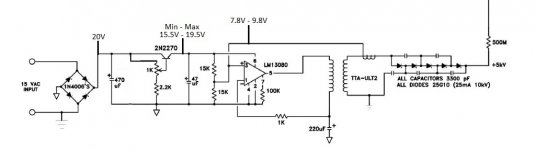
A note on the schematic: the labels for the red and orange bass taps are reversed: my mistake when I drew it some 25 years ago.
The purpose of the 1-ohm resistor is to limit the minimum impedance at very low frequencies. It should always be present for maximum stability with your amplifier. As this resistor is bypassed with capacitors, thereby removing it from the circuit at high frequencies, its quality is not vital. However, if it needs to be replaced anyway, it's not much extra trouble or expense to replace it with a more robust part like a metal-bodied resistor, made by Dale/Vishay and others.
The bias voltage is the same for all Acoustat speakers, so any information about one model will apply to all. If you cannot get the voltage high enough in one speaker, you may need to perform a simple modification to the circuit. Let me know if you need more information (this mod applies only to the earliest Spectra models). Otherwise, you may have an issue with one of the voltage multiplier's diodes or capacitors.
The value of the capacitance bypassing the 1-ohm resistor is critical only if using the speaker in the 'Above 100-Hz' mode. If the speaker is being used full range (or is utilizing an external crossover) the total value of the capacitance can be dropped to around 20-uF. This greatly reduces the expense and physical challenge of stuffing a huge polypropylene cap inside the interface.
Bi-amping the Spectra series is not advisable, at least not in the usual sense of splitting high and low frequencies and driving with separate amplifiers. My advise is to leave that aspect alone and drive the speakers as originally intended.
A note on the schematic: the labels for the red and orange bass taps are reversed: my mistake when I drew it some 25 years ago.
The purpose of the 1-ohm resistor is to limit the minimum impedance at very low frequencies. It should always be present for maximum stability with your amplifier. As this resistor is bypassed with capacitors, thereby removing it from the circuit at high frequencies, its quality is not vital. However, if it needs to be replaced anyway, it's not much extra trouble or expense to replace it with a more robust part like a metal-bodied resistor, made by Dale/Vishay and others.
The bias voltage is the same for all Acoustat speakers, so any information about one model will apply to all. If you cannot get the voltage high enough in one speaker, you may need to perform a simple modification to the circuit. Let me know if you need more information (this mod applies only to the earliest Spectra models). Otherwise, you may have an issue with one of the voltage multiplier's diodes or capacitors.
The value of the capacitance bypassing the 1-ohm resistor is critical only if using the speaker in the 'Above 100-Hz' mode. If the speaker is being used full range (or is utilizing an external crossover) the total value of the capacitance can be dropped to around 20-uF. This greatly reduces the expense and physical challenge of stuffing a huge polypropylene cap inside the interface.
Bi-amping the Spectra series is not advisable, at least not in the usual sense of splitting high and low frequencies and driving with separate amplifiers. My advise is to leave that aspect alone and drive the speakers as originally intended.
Good information, thank you Andy.
I had stated in my original post that one of the two boxes had a 10 uF electrolytic in it. Upon closer inspection this was incorrect. It was actually a PP film wrapped in an aluminum foil material. It looked liked one of those old silver axial electrolytics when I first saw it.
I have had a pr of the Acoustats Spectra 11....in the 2 interfaces one had one type of cap an the other had a diff cap...an thay were stock....that why when you saw diff i said nothing....but then again there only a crossover cap for none fullgrang....in your case....most run full...even with a added sub...
121 bass tarn.................2red..........3org...........4yelo....
Spectra...........2123..... 3-33-3300..org......2-22-2200.red.......i think Andy said the 44-66 had diff tran...my Spectra 3s are on org....................But Andy well say
Spectra...........2123..... 3-33-3300..org......2-22-2200.red.......i think Andy said the 44-66 had diff tran...my Spectra 3s are on org....................But Andy well say
Attachments
![modC_v2[2].jpg](/community/data/attachments/405/405617-034441492604235ef966e9126e513f18.jpg)
Last edited:
Andy
Just to make sure I understand this the correct transformer wiring should be
Spectra 3300 = RED
Spectra 2200 = Orange
Thanks
Andrew
Note 4 on the drawing is CORRECT - it's the labels on the schematic that are backwards. The RED tap is for two-panel speakers, and the ORANGE tap is for three-panel systems. Sorry for the confusion.
Note 4 on the drawing is CORRECT - it's the labels on the schematic that are backwards. The RED tap is for two-panel speakers, and the ORANGE tap is for three-panel systems. Sorry for the confusion.
Corrected(I think) drawing attached...please confirm.
The Spectra sector wiring and bass equalization notes may prove helpful for the OP as well.
Attachments
Corrected(I think) drawing attached...please confirm.
The Spectra sector wiring and bass equalization notes may prove helpful for the OP as well.
The attached schematic is now correct. Thanks.
I had a odd dream last night wherein an Acoustat owner sent me a check for $400 in appreciation of helping him with a question about his speakers. Okay...who needs my mailing address?

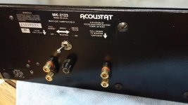
I have finally received all of the parts and began working on going through these Acoustat boxes. I included some pictures of the first box I completed. All caps were replaced, new binding posts, higher capacity 1 ohm Vishay resistors, and new switches. If anyone wants to replace the switches in these interface boxes, they are still available. Honeywell produces an identical drop-in switch (Part #12TS115-3), Mouser carries them at a cost of about $13 ea. The new switches are rated for a higher capacity, the old ones were 15A/125VAC/.75hp, the new ones are rated for 20A/125VAC/1.5hp.
The 100uF/100v NP electrolytic in the crossover had leaked electrolyte out of the lower side of it. It turns out the 47uF in the network was only rated for 50V. I was wondering why it was so much smaller than the 100uf, but the voltage rating was facing downwards so I couldn't see it. I'm sure that one was run well beyond its rated voltage capacity at some point in the past.
The binding posts are a bit of a pain because of the fact Acoustat designed the backside of the posts to be the support for the main x-over board. This greatly limits your options for replacement unless you would like to completely redesign the support scheme. We decided to go with these posts that are of a similar design as the originals, but with better quality gold plated brass parts and a larger cable capacity.
Attachments
Okay guys I have a few questions for the Acoustat experts.
I am setting up the bias on these 2123 boxes and they are both a good bit low. I have the ultrasonic boards mounted in the chassis as the instructions state to do. These have the 15VAC adapters. I am checking them with both a 1000X probe and simultaneously with a second meter hooked up directly to the red taps. The lower voltage reading on the second meter with the 1000X probe disconnected maxes out on the first box at 68VDC and the second at 65VDC. Once I connect the 1000X probe to the 5KV tap the supply loads down to about 55VDC at the red tap and I measure about 3kv on the 5kv tap with the 1000X. So even accounting for the loaded tap I only have maybe 3600V without the 1000X probe connected. This seems extremely low compared to the 4300V I need.
Reading through the info on Andy's site I see that too high of a voltage can be an issue and a change to a lower voltage zener on the ultrasonic PCB is needed to correct that issue. Is it possible the opposite is true here? Do I need to switch that zener out for a modestly higher voltage? At this point I do not know which voltage zener is in there. I would have to drop the pcb out to determine that.
The good news is of course they are both off by approximately the same value so there should be no component failure involved.
The bias board in these boxes differs from the schematic. There is no zener, a jumper is installed in its place and likewise no 470 ohm limiting resistor. I am assuming the zener and resistor were removed to allow for higher operating voltage as now the full DC rail is able to reach the base of the regulation transistor. I modified the schematic as previously supplied to account for the boards installed in these boxes. I also measured the voltage at a few points in the circuit and put those measurements into the schematic. The voltage measurements seem as expected. I am however surprised that I can get that high of a voltage out of the reg transistor, I expected at least a 1 - 2V loss.
BTW Michael told me that this low bias voltage was an issue before the upgrades, so whatever the issue is it started before the work that was just completed.
BTW Michael told me that this low bias voltage was an issue before the upgrades, so whatever the issue is it started before the work that was just completed.
Attachments
Last edited:
I think that I am slowly piecing this puzzle together.
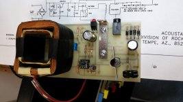
I found this article on audio haven about upgrading the US board. Due to the fact this board has the 4.7uF capacitor, .001uF film cap and no HV feedback wire attached it looks like this is one of the very early boards. The date codes of the electrolytics I replaced were '87 & '88. So it appears that what I need to do is to convert this older rev board to match the newer rev schematic that is posted here in this thread. I'm surprised that all of the holes and component silk screening is there to make it the newer 1991 rev, but none of those components are present. What's up with that?
In addition, While measuring I left my meter checking voltage on pin 3 of the IC and decided to check the 5KV tap with the 1000X probe and the HV had climbed to 3.7KV with just the loading of the meter on that IC circuit. When I pull the probe off of pin 3 of the IC the HV drops back to 3KV, so the circuit appears capable of operating as intended.
I included a picture of the board I'm measuring.
Attachments
Last edited:
Yea...i saw that The board was diff....maybe Andy can say.... send him a e-mail....i have never seen that board...
Driving the panel Transf with that low bias is not good!
3k is low....
But where is the 500m...? the end of it is were to put the probe? ......... is the 500m on a nother board?
i run my panels... more like 4.7-5k.........youll get 3-4db more output with the high bias
thanks for the pic
Driving the panel Transf with that low bias is not good!
3k is low....
But where is the 500m...? the end of it is were to put the probe? ......... is the 500m on a nother board?
i run my panels... more like 4.7-5k.........youll get 3-4db more output with the high bias
thanks for the pic
Last edited:
But where is the 500m...? the end of it is were to put the probe? ......... is the 500m on a nother board?
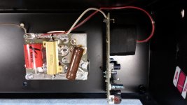
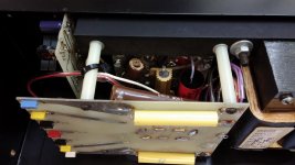
Yes, the multiplier and 500M resistor are on a second larger board.
But where is the 500m...? the end of it is were to put the probe? ......... is the 500m on a nother board?
Here is a picture of the two boards.
Attachments
- Status
- This old topic is closed. If you want to reopen this topic, contact a moderator using the "Report Post" button.
- Home
- Loudspeakers
- Planars & Exotics
- Refurbishing Acoustat 2123 interface, have ?'s