. It looks to me..just add 2 more doids an 2 more caps on the big board
then use the pot to back off are add more bias....right?
I will hold off on reengineering the thing for now. I'm just going to update the ultrasonic board to the later version with the Zener emitter follower regulator, the changes to resistors and capacitors and adding the antenna wire. I will be surprised if it is not working once those changes are made. Like I said earlier, just loading the ultrasonic pcb circuit with my meter caused a jump of over 20% in the HV output. So I'm pretty confident the issue is on that board.
I ordered the parts needed to make the changes. I bought both 10V and 13V zeners so I can drop to a lower voltage if I do not have enough HV adjustment. I'll update in a few days once I get one of the boards completed.
Did you e-mail Andy.....Hes the...........Acoustat Answer Man is here....last man standing who worket for Jim...here anyway....
.I have had minny Acoustats....An never seen your setup...Hehe
i have a pr of Spectra 3s but mine have the old bias in my 2123 plate.....My bias is like the ones in the 121......
Cant say if your right...but Andy has been glad too help us all...great guy....good luck what ever...
.I have had minny Acoustats....An never seen your setup...Hehe
i have a pr of Spectra 3s but mine have the old bias in my 2123 plate.....My bias is like the ones in the 121......
Cant say if your right...but Andy has been glad too help us all...great guy....good luck what ever...
Last edited:
First, I highly recommend that you upgrade the circuit as described in my article. It can't hurt, and is likely to improve the situation. This upgrade improves the stability of the oscillator and frequently will raise the maximum output voltage. There were some interim 'solutions' to this problem, so you may see some variations in the circuit before this final upgrade was done.
Don't try to measure the bias voltage with TWO meters (of any sort) connected simultaneously. This will seriously load the supply and give you a false reading.
Due to the high impedance of the circuit, ANY standard meter or HV probe will load the circuit, and will indicate a lower-than-actual voltage. How much error there is will depend on the impedance of the measuring device. So don't give overly much importance to the absolute measurement: it is far more important to achieve the same measurement for each speaker.
So go ahead and do the upgrade and report back what you find. It would also help to know more about the input impedance of your two meters to help judge your actual readings.
You may see recommendations to raise the bias voltage higher than factory settings. You are welcome to follow that advice, or at least experiment, but my advice is to leave it at the original value.
Andy, Thanks for following up on the thread and for the valuable input.
To answer your questions about my meters/probes. I am using a Tektronix 100Meg Ohm 20KV HV probe. Both of my meters, a Fluke 77 and an old Micronta, are 10 Meg Ohm when set to the voltage range I am using.
I received the parts from Mouser and upgraded one of the ultrasonic boards tonight and there was little difference between the upgraded and non-upgraded board approx. 100V increase as measured by the HV probe. I connected the scope and used the HV probe to check the waveform (red wire connection) before the voltage multiplier circuit and I have about 1400V - PEAK TO PEAK, at about 21khz. I assume that the 100 Meg ohm load of the HV probe will affect the freq and lower the voltage of that reading somewhat.
I also checked the DC level of each multiplier stage and they are evenly stepped, none of them are showing lower than the others.
I am going to sleep on it and try to come up with some fresh ideas. I'll accept any fresh ideas as well....
TYU, I haven't taken the additional multiplier stage idea you mentioned off the table yet either.
I forgot to mention in my previous post that I also tried adjusting the voltage divider feeding the non-inverting input of the op-amp. The board originally had two 12k resistors as the divider and I followed the newer schematic and installed a pair of 15k ohms in their places. Once I realized the HV output was still low I then tried both slightly lowering and raising the resistance tied to the + voltage rail to see if altering the DC at the non-inverting input would have any effect. Lowering the resistance to 9k had zero effect, raising the resistance to 20k caused a slight loss in HV output of about 7 - 8%.
I also tried cleaning the multiplier board. I started wondering if the board had become dirty over the years and was putting an additional load on the HV. I used to work on ion implanters which operated as high as 160kv and this was occasionally a problem on those HV systems as they aged. So I cleaned all of the old solder resin off the board and sprayed it down on both sides with some board cleaner and scrubbed it with a soft brush. Retested and no change to speak of, oh well it was worth a try...
This evening I am going to check the LV signals around the opamp with the scope. As it stands it looks like I need to boost the output signal from the opamp to get the HV up to where it needs to be.
You won't be able to get accurate voltmeter measurements due to loading since the impedance of your test equipment is much lower than the impedance of the ESL panel.
You could set your Fluke 77 to measure uA and place it across the output of the HV supply after the 500M resistor; you will be measuring load current through the 500M resistor. If the supply can drive a 500M load without too much loading, you should measure 5kV/500M=10uA. Better yet, get a 500M resistor and place it in series with the 500M output resistance; this will further decrease loading, and you should measure 5uA.
You measured 1400V PP at the input to the multiplier. This should give 4.2kV output, so you supply is probably working just fine.
My real concern is not so much the reading with the 100 Meg HV probe. I accept that this HV probe may be too much of a load for the supply and give me low readings. My main concern is the reading with the 10 Meg DMM connected from the red tap to ground. This seems like a well established setting at 75 volts and it seems that many can actually adjust higher than that reading. The measurements of these boxes seem much too low at 65 and 68 volts maxed out. I would feel a lot better if I could at least get these things up into the low 70 volt range when measuring off the red tap.
This is my first interaction with Acoustats so definitely tell me if I'm chasing my tail here. I just want to make sure that these interfaces are correct when I give them back to Michael. I don't want to throw in the towel if there are more things I can check.
According to the specs it looks like the lower end of my Fluke 77 for amperage is 10 uA so that will likely not give me an accurate reading. My old Micronta appears to be 1 uA capable so I'll give that a try tonight.
Well I finally figured it out folks. I must have pulled that damned ultrasonic board at least 40X in the process.
It kept bothering me that I was able to get a > 20% jump in HV output when I touched my 2nd meter leads to pin 3 of the op-amp a few nights ago. I kept thinking the op-amp wasn't getting enough of a signal. So I tried adding about 12 extra turns to the antenna lead on the HV wire. This resulted in a jump from 65 VDC on the low measuring of the two interfaces up to 68 VDC. I tried adding more wraps on the HV lead for the antenna but it only got worse from that point. In the end I ended up with about 20 wraps of the antenna wire on the HV lead.
I then took the higher measuring interface box of the two, which still had the non-modified US board. I hooked it up and maxed out the voltage on it at 68 VDC on the red tap. I then touched a disconnected (floating) meter lead to pin 3 of the op-amp and the voltage jumped to 81 VDC. This told me that it too was needing more signal on the op-amp input. I wondered why this box was measuring so high now and the other modified box wasn't. The main difference was the lower DC rail voltage. So I decided to go back to the other interface box and remove the zener and short the 470 ohm resistor. This would allow full rail voltage to make it to the base of the transistor like the higher measuring interface box. After the changes I remeasured the old lower measuring interface and it was now putting out 83V on the red tap and I couldn't adjust it below 78 VDC with the pot.
I had a couple of 15V zeners so I put the 470 ohm resistor back into the circuit, installed a 15V zener and swapped the 2.2k ohm resistor out with the original 5600 ohm to drop the current through that leg of the circuit. The interface box measures perfect now. I have full adjustment from 73 VDC - 78VDC at the red tap.
The scope shows the output of the good measuring board before the voltage multiplier to have jumped from 1400V P-P to a level of 1800V P-P now after the changes. That is with the board setup for 75vdc at the red tap, so it would be higher if I maxed the pot out.
I plan to tweek the unmodified US board to match the good measuring one tomorrow.
In the end it appears that the issue was twofold. Not enough dc voltage from the regulator circuit and not enough of a signal to pin 3 of the op-amp.
Last edited:
Outstanding, Kevin!
I was confident you'd figure this out, but was getting pretty irritated that it was taking you so long.
Honestly, I was about ready to tell you to not worry about it and send them back to me. I never imagined it was going to be such a PITA but your talent and tenacity really came to the fore and put this thing to bed. Now maybe I (we) can hear what the big damn deal is everybody makes about these things.
Ok.....you guys...Dont forget to let us all know what you think about the sound??
The Bias i use on my Acoustat Can be set from 4-7k....only time it needs to be set diff is when the humity get high....if it dry...these thing go up in output an the stock setup is right on the money.....to low bias an the sound get Darker..More bass ...rold off highs....to much bias...sound gets hard sounding. top gets sharp..the mylar is so lite...the humity lodeds the output down...
.This gos for all Mylar baset drivers i have found...
Acoustat,SoundLabs,MartanLogan,....Even Magnepans...It can be a pain....But when all thing are working right.....theres know Better... or Realer Sound!...
When high humity happens i pull out the Apogees,Magnepans.....are trun on the AC....
Long Live Acoustats.....
Last edited:
After spending a good bit of time tweeking these Mk-2123 interface boxes I have a little more info for anyone that might come along and read this in the future with bias voltage issues.
A recap if you will....
First, If your interfaces haven't been upgraded to the newest revision that is posted on Andy's site then I recommend you do this first. The quick way to know is if the bias boards have the antenna wire wrapped around the HV lead or not. The boxes I worked on did not have the antenna leads.
If your bias boards are already upgraded then you may still need some parts including a range of zeners, and a couple of resistors. You may also need to consider replacing the antenna wire with a longer one to allow more wraps of the antenna lead on the HV wire(see below).
If you are buying parts to do this upgrade, I would buy several different voltage 500mW zeners, 10, 12, 13V, 15V, & 17V. They are so cheap you might as well buy a variety of them to give yourself the maximum flexibility. If you are buying resistors to replace the 5600ohm resistor with a 2.2k ohm as the schematic shows, also get 1.2k, 1.5k, 2.5k and 3k ohm resistors. You need 1/4watt rated resistors minimum for this as the higher rail voltages with the 15V and above zeners will pass a good amount of current through the 1.2k and 1.5K resistors. I used Dale RN60’s, which are military rated at ¼ watt and supposedly good for 1/2watt. Once again, the different resistors are to give you the ultimate flexibility with your bias adjustment. Install the 2.2k ohm resistor and the 13V zener as shown in the schematic to start with. You might want to measure the voltage to see what zener you currently have in your Ultrasonic bias board circuit.
I would recommend that you add several wraps to the HV antenna lead, start with 10-12 wraps and leave an extra 6" or so of wire so you can add wraps if needed. Try to keep the loops tight on the HV lead! Once the board upgrade is completed and the initial antenna wire wrapping is performed then install the board into the chassis. Ensure that the extra length of antenna wire is safely placed so it cannot come near the HV section. Do not cut off the excess antenna lead yet.
Set your meter for DC volts and clip your leads onto the RED tap (Not the point labeled HV 5kv) and chassis ground. Then power the interface ON.
If the bias voltage reading on the Red tap to chassis ground is TOO HIGH even with the pot at its minimum level then you have two options. #1 - POWER OFF & DISCHARGE THE BOX, Then you can change the 2.2K ohm resistor with the 1.5k or 1.2k ohm resistor. This will allow for even lower bias voltages by approx. 5 – 10Volts lower than you measured, but will leave the maximum bias voltage you measured unchanged, OR #2 POWER OFF & DISCHARGE THE BOX – If you need even more drop in bias voltage then you can change the 13V zener out for the next lower rated voltage you purchased, the 12V. The lower voltage zener will drop both the maximum voltage and the minimum voltage, so the whole adjustment range is affected. Weigh your options and change as needed.
If the bias voltage reading on the Red tap to chassis ground is TOO LOW even with the pot set at its maximum level. You have two options. POWER OFF & DISCHARGE THE BOX, then #1 – Add additional wraps to the HV lead with the antenna wire(you left some slack wire right?), I would try 5 additional loops at a time. Then power the interface back ON and see if the maximum voltage increased appreciably, like another 1V or more of maximum bias. If it increased then power the box OFF again, discharge it, and add more loops, retest, repeat. Once the voltage seems to level out, cut off the excess wire and seal the loops up with heatshrink. I also recommend that you position the loops in such a way as to stay away from the small board mounted HV transformer. In my testing I found that the bias voltage tended to drop several volts when the loops were next to the transformer.
If adjusting the antenna lead loops does not help with increasing the low bias voltage to an acceptable level then #2 POWER OFF & DISCHARGE THE BOX, Install the next higher voltage rated zener into the circuit. Remeasure your bias voltage, if the maximum bias voltage is now good, but the adjustment range will not let you drop it enough then see the previous section about resistor replacement.
In extreme low bias cases you can eliminate the zener altogether and allow the full 20V DC rail to pass through. To do this, remove the 470 ohm resistor and install a jumper. Remove the zener and leave the space empty. I would recommend a ½ Watt rated resistor or a Dale RN-60d below the potentiometer in the schematic (the 2.2k), especially if the 1.2K or 1.5K ohm resistors are going to be used at the 17V or higher voltage level. Also space the resistor off the board a bit to allow for good cooling.
The lower value resistors are great for dropping the minimum bias voltage, but they have a negative aspect as well. They will make the potentiometer much more sensitive, small changes in potentiometer position will result in larger changes in bias voltage. If it turns out you have too much adjustment range, you can install a resistor value higher than 2.2k to minimize the bias voltage change and subsequently minimize any drift that might occur over time if resistance changes in the potentiometer.
Hopefully this info helps someone out in the future....
Chamberman-
Thanks for posting your observations and advice.
At the Acoustat factory, we never found it necessary to wrap more than a few turns for the feedback 'antenna'. However, I see no harm in adding a few more turns as you have done. A bit of heat shrink tubing is advisable to keep the wire tightly wrapped.
I'm not crazy about the idea of removing the zener diode, as this eliminates one of the primary advantages of the ultrasonic supply, in that it is a REGULATED supply. However, I wouldn't expect this to be necessary except in extremely rare cases of very low bias. And even then, I would investigate other possible causes of low bias before removing the regulator.
Chamberman-
I'm not crazy about the idea of removing the zener diode, as this eliminates one of the primary advantages of the ultrasonic supply, in that it is a REGULATED supply. However, I wouldn't expect this to be necessary except in extremely rare cases of very low bias. And even then, I would investigate other possible causes of low bias before removing the regulator.
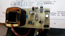
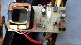
That is interesting because as I stated in one of my earlier posts these early rev ultrasonic boards were built in just that way with the zener left out and a jumper in the 470 ohm resistor position. You can see this in my pictures of the two ultrasonic pcb's shown in my previous post. I am sure they came from the factory this way because the solder pads for the empty zener position were pristine.
I won't claim to remember everything we did at Acoustat over 20 years ago, so it's possible that the 'no-zener' change was made to a few early units when we were having trouble with the stability of the circuit. There were several early variations of both the circuit and the transformer before it became stable in both design and operation. Funny how the final version used fewer parts - how often does THAT happen?
Even if I had authorized the 'no-zener' change (and if it came from the factory that way, I almost certainly DID authorize it) I would not have been happy with that change then, either. It's meant to be a regulated circuit to avoid any performance changes based on mains voltage variations. Sometimes we do things we'd rather not, in an effort to ship product and generate revenue. I recall a lot of tension during that time while we were fighting that circuit AND trying to ship speakers.
Now I can relax and bask in the glory of what Acoustat was, and still is for so many people. And that's why I'm here as the Acoustat Answer Man.
As far as I know/found out, too high a bias voltage is only a problem when the panels start making noise with no amp input. As long you have same bias voltage on both speakers, and as high as possible, that's when you are set.
I have upped the Bias on my 2+2 and they sounds great - more spl and better highs. That's how they set the bias on Soundlabs - raise bias knob until you start hearing crackles, then slightly back off....
I have upped the Bias on my 2+2 and they sounds great - more spl and better highs. That's how they set the bias on Soundlabs - raise bias knob until you start hearing crackles, then slightly back off....
- Status
- This old topic is closed. If you want to reopen this topic, contact a moderator using the "Report Post" button.
- Home
- Loudspeakers
- Planars & Exotics
- Refurbishing Acoustat 2123 interface, have ?'s