Please see the attached diagram on my Medallian transformers.
Have never measured, and was wondering what the bias voltage is.
Where do I put my test probes,
I'll unplug the unit,discharge the panels and use leads with alligator clips before re-plugging in and measuring.
Thanks,
Paul
Have never measured, and was wondering what the bias voltage is.
Where do I put my test probes,
I'll unplug the unit,discharge the panels and use leads with alligator clips before re-plugging in and measuring.
Thanks,
Paul
Attachments
What i have done with the Stock Acoustat bias.... make a bias outboard box you set 4-7k............
So this mean geing bias out of the Box were the stepup tranX an res. 50k 50watt an the .1 caps are....
Stray eddys are alover the board look at the pic...1" from the driver res an caps...Driveing the panels can pull the bias Down....you get much better output out of the Panels......An the Acoustats are well worth it.
But if you wont to stay...With stock bias setup.....that i have found all low.. like 4k.....after being feed Ac-Dc all the time for what over 15 years.....
I have found this after owning 20 Acoustats panels for over 30 years
Drop the bias 500 meg to 15-20meg...get the bias up.....you Can get 3db more output...an the setup transfourmers An parts...well run a lot cooler....an you may get 20-50 more years out of the Acoustats.....
Long live Acoustats
Attachments
![212688d1299318205-acoustat-answer-man-here-red-medallion-c-solen%5B1%5D[1].jpg](/community/data/attachments/378/378907-1ad34e90a51c5f4dcab282ca9f2d4904.jpg)
Last edited:
Please see the attached diagram on my Medallian transformers.
Have never measured, and was wondering what the bias voltage is.
Where do I put my test probes,
I'll unplug the unit,discharge the panels and use leads with alligator clips before re-plugging in and measuring.
Thanks,
Paul
The best way to measure the bias voltage is with a high-voltage probe, and this is the way that Acoustat's factory verified the voltage. This is done by connecting the probe's negative lead to the high voltage ground, at the center rear of the printed circuit board. The positive lead is connected to the red tip-jack, that is, after the 500-megohm resistor. However, due to the high output impedance of the supply, and the loading effect of the probe, you will typically measure about 3000-3500 volts when the supply is actually putting out about 5000 volts. The measured voltage will vary with the impedance of the probe, so different brands/models will yield different results. Therefore, this method is not so much for measuring the exact voltage output, but it is useful for troubleshooting, and/or verifying that both interfaces are operating the same.
A digital voltmeter with a 10-megohm input impedance can also be used, with the same connections as above. In this case, the meter will read about 90-volts due to the meter loading the supply. Again, this method will not yield actual voltage, but it is useful for comparing two interfaces.
A variation of Heisenberg's Uncertainty Principle applies here - due to the high output impedance of the supply, it is virtually impossible to measure the voltage applied to the diaphragm without changing that voltage.
The method mentioned in another post is okay (measuring the voltage across the first diode, and then multiplying by five), but will also yield results that are more relative than exact. However, that method will not verify the proper operation of the 500-megohm resistor.
I am also not a big fan of increasing the bias voltage, but others have differing opinions. Decreasing the value of the 500M resistor by a significant amount will take away from the very important constant charge operation (and thereby increase distortion). If you needed to replace the resistors, and couldn't find 500M, then a several-hundred megohm resistor would still be okay, but I wouldn't go lower than that. Otherwise, if your resistors are okay, I would recommend sticking with the stock values.
Likewise for the bias voltage, Acoustat did extensive research in arriving at the optimum bias voltage for the speakers, which is a good compromise between efficiency and potential arcing problems in high humidty/high altitude conditions. Increasing the bias voltage WILL increase the efficiency, but at the expense of possible problems with arcing under high-drive conditions.
I have posted many times on how to build a device to very accurately measure such voltages.
The whole thing would cost but maybe about $10 with parts from your local Radio Shack store.
However it would have to be measured before the 500Megohm resistor.
Or measure the 500Meg resistor for it's exact value and include that into the voltage divider calculation and use another resistor to ground to give you a 1000:1 voltage drop,
Then the reading on your meter across the new resistor to ground would be 1V per 1000V.
Using an opamp buffer will eliminate any errors due to the meters input resistance.
http://www.diyaudio.com/forums/plan...me-fix-these-poor-ml-sequels.html#post3775769
FWIW
jer")
The whole thing would cost but maybe about $10 with parts from your local Radio Shack store.
However it would have to be measured before the 500Megohm resistor.
Or measure the 500Meg resistor for it's exact value and include that into the voltage divider calculation and use another resistor to ground to give you a 1000:1 voltage drop,
Then the reading on your meter across the new resistor to ground would be 1V per 1000V.
Using an opamp buffer will eliminate any errors due to the meters input resistance.
http://www.diyaudio.com/forums/plan...me-fix-these-poor-ml-sequels.html#post3775769
FWIW
jer
Last edited:
Yes, If you know your meters input resistance you can closely calculate the voltage.
Do have the ground lead connected to your meter First before attempting such measurement technique.
If you don't then there is the possibility of harming your meter as it will be energized at a 5Kv potential without the ground lead
connected.
Using the link to the online calculator I provided will allow you to include the meters input resistance as well into the calculation.
It needs to be much higher than the bottom resistor in the chain.
you would surprised in how much of a difference of an error it can make it you don't.
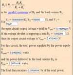
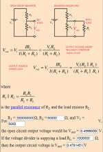
Using a 50K resistor from the 500meg to ground will give you a reading of .5V for 5Kv (.1V per 1Kv) across it on your meter and will be fairly accurate if your meter has an input resistance of at least 1Megohm or greater.
With a 1Megohm meter input resistance the voltage reading error will be about 4.76% lower than the actual value with the above method.
jer
Do have the ground lead connected to your meter First before attempting such measurement technique.
If you don't then there is the possibility of harming your meter as it will be energized at a 5Kv potential without the ground lead
connected.
Using the link to the online calculator I provided will allow you to include the meters input resistance as well into the calculation.
It needs to be much higher than the bottom resistor in the chain.
you would surprised in how much of a difference of an error it can make it you don't.
Using a 50K resistor from the 500meg to ground will give you a reading of .5V for 5Kv (.1V per 1Kv) across it on your meter and will be fairly accurate if your meter has an input resistance of at least 1Megohm or greater.
With a 1Megohm meter input resistance the voltage reading error will be about 4.76% lower than the actual value with the above method.
jer
Attachments
Last edited:
Andy post.....
Again, this method will not yield actual voltage, but it is useful for comparing two interfaces
So What do you do if the two 121 interfaces are not the Same but all parts are working??................
As always thanks for your input on the Acoustat interfaces an bias....
I get LESS Arcing.... with the 500meg dropet to 20meg....an a good 3db more output out of the panels......less stress on all the interface parts.....best sound i have ever got out of the Acoustat panels........
When the panels were new....25 years a go....5000meg may been fine....but in my M3s the interface even with the bias raised......can boog if push hard....an parts get hot!......i would think this is from loseing some of the bias coating on the mylar...
I now think wasing the Acoustat panels.... is NOT a good thing...
If you look at this pic....thats not dreat.....that dark water....is cothing....coming off...........good luck
long live Acoustats.........
Attachments
![AcoustatPanelsBathing[1].jpg](/community/data/attachments/379/379684-d380c80412bc89798a59563e15d4096a.jpg)
Acoustat had a coating resistance of about 50K ohms so washing off coating is not a bad thing remember that Quad are many meg ohms so the higher resistance will keep the charge stable on the diaphragm and not let voltage run around to jump off at the closest stator with a leak in the dielectric. Must my 2 cents on that topic. Best regards Moray James.
So when the Panels being driven hard....what happens....the bias is pull off the cothing....used up?...it being driven off?...an has to catchup?
Is this why i am finding that lowering the bias feeder res. in the 121 stock is 500meg.....to 30meg that there is less... arkover an less stress on the tranfoumers an res. in the interface?....An Amps geting HOT.....
I have done the same on some of my MLogans bias.... drop the stock 60meg...20meg ....an thay sound like my Acoustat now.... some thing i have never heard....out of any ML panel!
go fig....
I see it like 1/4" pipe feeding a tank....so i just put in a 1" pipe...now the panel output ... can keep up with how had there being driven....NO booging?
Tell me why droping the MEGs.... is a bad thing...?
As always... thanks for your time an any info on ESLs...Bias..
Tyu, add to your observations of decreasing the resistor value, the additional complicating findings of people who suggest adding a large value choke between the resistor and the coating on the membrane.
That will increase resistance, but only by a little (relatively). And should impede the flow of current onto the membrane if the charge is reduced from playing (or just with time).
Was that you that recommended that Moray James? That was a while ago.
Do you still a recommended this tweek?
Thanks
Paul
Adding the Choke Makes sense to me.
The reason is that as the diaphragm is moving I have found that this does modulate the bias level a bit.
Having a choke in line will stop this A.C. content from feeding back into the supply therefore allowing the supply to maintain a constant level.
This is one of the reasons I have chosen to build a feedback circuit to regulate my HV supply.
Just the slightest amount of current draw can significantly drag down the bias voltage by as much as 5% or even 10% or more, especially if the supply only has a 60Hz refresh rate.
If the panel has absolutely no leakage then the size of the resistors should have no effect on the bias charge on the diaphragm.
But they will help stop the A.C.content from modulating the bias supply.
I have proven this in tests with my scope monitoring the Bias Voltage.
Putting a resistor on the ground side of the bias supply feeding the transformer also reduces this effect even more.
I am not sure how much this would effect the THD but it may have a bit of results on the IMD factor.
FWIW
jer
Last edited:
Will the choke dose help....
Moray was the one that came up with the Choke Mod!
I have been Diying tube amps OTL an push pull....an have found that chokes have there owen sound to add......most chokes Ring......in tube amps...i am finding that to get the sound i have been looking for over 40 years is to use the choke on the front end only.. way less ringing..... but Not the output tubes....not saying chokes dont work...but you better have a well made Choke!....$15-20..... not going to cut it....just like the ESL bias...it is the sound of the ESL...better parts in the bias well give better sound!....
An yes i have know dout that the THD must go up when lowering the Res. in the bias...but the sound..May be it the more THD that makes the sound better..
I now think it not raising the bias. so much....to get better output...
We may even get by with less bias....but get the res. to about 20-15meg...
One thing this Mod has done for the ML.... i have been in a lov-hate with for ever.....
is move there sound so close to the sound of my Acoustats....that the logans have moved to front place...even giveing my Apogees stages... a run for the money...an the Output....50 tube watts driven them with eezzs............
You dont know if you dont go.....you can always add megs....have fun...it all just about geting the best sound....from your ESL
- Status
- This old topic is closed. If you want to reopen this topic, contact a moderator using the "Report Post" button.
- Home
- Loudspeakers
- Planars & Exotics
- How to measure bias voltage on Acoustat