So here's an update.
I checked all the solder joints on the crossovers and fixed the bad ones I found hooked up the power supplies and reinstalled them into the speaker hooking them up the way they came out.
I hooked them up to a test amp I have and plugged them in, turned on the amp and turned on Pandora. At first nothing but then I jiggles the speaker leads and suddenly I had sound. Unfortunately it wasn't anywhere near as loud as it shows have been and it was only coming out of the panels. No bass. Hooking up the speaker leads directly to the bass leads I get music out of the bass drivers but not with them hooked up to the crossovers. Another thing is regardless of whether the speaker power supply is hooked up or not it makes no difference. Same low level sound. It sounds ok. Mid to upper frequencies but nowhere near enough volume. Flipping the "on/off" switch on the power supply also makes no difference.
Ideas?
Thanks
Eric
It seems to me that the Bias supplies are not working.
You can get sound out of an ESL without them due to a very small charge that may be on the diaphragm, But it won't be very much as you have experienced.
You need to build a resistor divider in order to measure the high voltage as I had suggested earlier.
You can however do a simple arc test through a at least a 30megohm resistor (3 X 10megoms in series) from the output of the supply to ground.
If it is working than you should get an arc to jump about a 3-4mm gap.
Check the diodes in the supply for any leaky or shorted ones.
jer")
You can get sound out of an ESL without them due to a very small charge that may be on the diaphragm, But it won't be very much as you have experienced.
You need to build a resistor divider in order to measure the high voltage as I had suggested earlier.
You can however do a simple arc test through a at least a 30megohm resistor (3 X 10megoms in series) from the output of the supply to ground.
If it is working than you should get an arc to jump about a 3-4mm gap.
Check the diodes in the supply for any leaky or shorted ones.
jer
So it's a good sign that I get sound out of the panels, correct?
It doesn't surprise me that there are issues with the crossovers given the condition they were/are in. Hopefully taking them apart and checking the components will get them working properly.
I will check the diodes and do a spark test. Can I test the transformer in situ and if so how?
Thanks
Eric
It doesn't surprise me that there are issues with the crossovers given the condition they were/are in. Hopefully taking them apart and checking the components will get them working properly.
I will check the diodes and do a spark test. Can I test the transformer in situ and if so how?
Thanks
Eric
When you try a spark test make sure that you are holding the ground wire and NOT the HV wire.
Else be ready for a JOLT !!!!
I don't know enough about ML's power supply's in order to give you specific things to check.
From your picture they look quite a bit different then any of the pictures I have seen posted in these threads.
If they are line driven then this would be easy but typically they are driven from some sort of high frequency oscillator.
This is not an issue for me, I am just not familiar with ML's circuit is all.
If you can obtain the actual schematic to the board you have then this will greatly help.
Else I will help with what I can.
Getting some sound is a good thing as this shows that the Step-ups may be okay.
But, After being driven to the point of burning up the crossover their integrity still has to be in question.
Getting the Bias supplies to work is the first step.
It seems by your picture that they are line driven with 4 stages of multiplication.
You can go by CharlieM's design as a reference for trouble shooting.
The links are in post #2.
You should have about 600Vac to maybe as high as 900Vac out of the transformer feeding the multiplier stage.
jer
Last edited:
It looks like there is already enough resistance on the board already.
jer
So I can run a pair of wires out of the blue terminal block and see if I can get an arc between the ends?
I do t want to fry anything
Thanks
Eric
So I get 335 volts out of the blue terminal block and a ver small spark but it doesn't jump anywhere near 6-7mm. More like 1-2mm.
I checked all the diodes and they all measure within a few % of each other. All the black ones between the caps and the four in the group of 16 diodes measure about 670+-. The redish ones measure about 820 and the tan ones about 830.
Should I be concerned about the PS transformer?
Thanks
Eric
I checked all the diodes and they all measure within a few % of each other. All the black ones between the caps and the four in the group of 16 diodes measure about 670+-. The redish ones measure about 820 and the tan ones about 830.
Should I be concerned about the PS transformer?
Thanks
Eric
They should not have any reverse leakage current what so ever...at all else they would be shorted.
Yes, you should be measuring the output of the transformer.
You are lucky that here wasn't any more voltage in the terminal block else you would be getting a new meter!!
I don't know what all of those other diodes and stuff are on the right side of the board do.
Could be a protection circuit of some sort.
You could easily draw out a schematic of that board with such few parts on it and that would help to trace it out.
The ones by the Orange cap's are the multiplier stage.
What exactly are you measuring 670-+,820 and 830 what?
Ohms, Volts, Vfr ( forward voltage drop)?
jer :
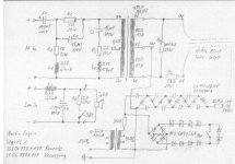
P.S. Here is the schematic !!!
http://www.diyaudio.com/forums/plan...-logan-sequel-ii-dead-panels.html#post3700785
Yes, you should be measuring the output of the transformer.
You are lucky that here wasn't any more voltage in the terminal block else you would be getting a new meter!!
I don't know what all of those other diodes and stuff are on the right side of the board do.
Could be a protection circuit of some sort.
You could easily draw out a schematic of that board with such few parts on it and that would help to trace it out.
The ones by the Orange cap's are the multiplier stage.
What exactly are you measuring 670-+,820 and 830 what?
Ohms, Volts, Vfr ( forward voltage drop)?
jer :
P.S. Here is the schematic !!!
http://www.diyaudio.com/forums/plan...-logan-sequel-ii-dead-panels.html#post3700785
Attachments
Last edited:
According to the schematic that supply should be producing close to 5.1 Kv.
5kv will jump at least 3 to 4 mm even if it is limited in current by the on board resistors.
The voltage across each diode in the chain will be approximately 635v if it is working properly.
There should be absolutely no resistance from any diodes when it is reversed biased,else it is a bad diode.
The same goes for any of the caps once they get fully charged by the meters power source they should show no resistance, IE~infinity.
Including any of the regular and zener diodes in the protection circuit as well.
It could be that one or more of these are bad dragging down the voltage feed to the multiplier stage after the 30K resistor.
The schematic shows it set for 230v input make sure that it is set for 115v input as I suspect that is what the switch near the transformer is for as it should be outputting about 450Vrms according to the print.
Make sure that none of the resistors measure open as well, such as the 30Kohm that is feeding the multiplier stage, it is highly unlikely that these will be bad anyhow.
It seems more likely a diode somewhere is shorted or a cap may be open or shorted some where.
You may have to pull one leg of each component in order to test it properly.
Welcome to the world of trouble shooting!!!
I used to fix TV's for a living and many times I would have nearly half of the powersupply section partly removed before I would find the the one or two bad parts.
70% of the time it was a bad diode !!!! He,he,he
jer
Last edited:
You need to test the output of the transformer from ground to either side the the resistor that is feeding the multiplier stage.
It is a 30k in the schematic but your values may be different, but should be close to the same range.
It should be in the 400Vrms to 450Vrms range coming out of the transformer.
If there is not then there could be an issue with the transformer.
I Don't suspect this as you are getting some voltage but the question is is it enough.
If there is voltage on one side of the resistor and not the other, the resistor may be open, or the zener diodes that are in the bottom right of the print after the resistor may be shorting the signal feeding the multiplier as it is at a very very low current.
You also should use the resistance function when testing diodes (and capacitors).
Diodes can seem to be okay in a Vfr test but still have a high resistance of leakage as well when it is reverse biased.
This is why you should use the resistance function too.
I have seen diodes show as much as 10K to 1 meg of resistance when they are reversed biased and this also would be a bad diode.
When transistors do this they often become noisy and/or distort the signal although they are still functioning....Somewhat.
It is possible that one of the caps can be open as well causing little to no voltage.
I have had my share of tracing down diodes and cap's in multipliers and sometimes I would have to lift one leg of each one in order to find the bad one.
The same goes especially with the cap's as the meter can't distinguish the flow of current through them with the diodes allowing the current to flow one way.
A scope and signal generator can help you with checking caps if you don't have a cap measuring function on your meter.
There are other methods you can use as well, as a cap will let an AC voltage pass through it but not a DC voltage and certainly not any voltage if it is open.
Yes, I have had cap's go open as well and this is what made it harder for me to fix even my own multiplier stages a few times, even though all of the diodes were okay.
jer
Quick question.
The schematic says the caps in the power supply are 100uF 630volt. I don't believe that is correct as the only I could find are over fourth-five dollars each and huge. I think they are supposed to be 1000pF 630 volt.
Please set me straight.
Thanks
Eric
The schematic says the caps in the power supply are 100uF 630volt. I don't believe that is correct as the only I could find are over fourth-five dollars each and huge. I think they are supposed to be 1000pF 630 volt.
Please set me straight.
Thanks
Eric
Last edited:
It is very hard to read but they are marked as 100nf on the print.
That would be .1uf (1000pf).
630v rating seems quite low and would be under the required rating if the transformer is actually putting out 450V !!
It wouldn't surprise me if a one of those are bad.
Use at least 1Kv to 2Kv caps if they need replacing the higher the better but then cost starts to become a factor past about 1500v.
jer
630v rating seems quite low and would be under the required rating if the transformer is actually putting out 450V !!
Although the transformer is putting out 450VAC, the resistor, diode bridge, and zener diode strings limit the peak voltage reaching the multiplier. The board contains 10 zener diodes (5 x 1N4756A and 5 x 1N4742A ). The total zener voltage depends on the switch position.
In the closed position two of the zener diodes are bypassed, resulting in 4 x 1N4756A and 4 x 1N4742A in series across the diode bridge; 4x47 + 4x12 = 236V. So, the peak voltage applied to the multiplier will be about 240Vpeak. The first capacitor will charge to 240Vdc and all remaining capacitors will charge to 480Vdc. The output of the multiplier would 240x8 = 1900Vdc.
In the open position, all zeners are in series across the diode bridge; 5x47 + 5x12 = 295V. So, the peak voltage applied to the multiplier will be about 300Vpeak. The first capacitor will charge to 300Vdc and all remaining capacitors will charge to 600Vdc. The output of the multiplier would 300x8 = 2400Vdc.
Check for any open resistors and the voltage out of the transformer feeding the multiplier stage before and after the resistor feeding it as I had mentioned earlier.
Bolserst had given the description of the action of the regulator zener diode section and should be about 170Vrms to 220Vrms after the resistor.
Make a 1:100 or 1:1000 resistor divider to properly measure the output of the supply.
A 10Megohm and a 10Kohm in series will suffice for a 1:1000 divider at 1/2 watt or greater, it won't be very accurate but it will tell you if you are getting anything close to 1KV or more with a reading of 1V per 1Kv on the meter across the 10K resistor to ground.
jer
P.S. I forgot that there are already some high value resistors on the board as well and you must include these into the calculation of the resistor divider too !!
This calculator can help you and it also allows for entry of the Meters input resistance so that you can get an accurate measurement,
http://hyperphysics.phy-astr.gsu.edu/hbase/electric/voldiv.html
Last edited:
- Status
- This old topic is closed. If you want to reopen this topic, contact a moderator using the "Report Post" button.
- Home
- Loudspeakers
- Planars & Exotics
- Help me fix these poor ML Sequels