depending on radiation condition velocity or accel are more nearly proportional to SPL
both near/far field and intentional cone breakup/frequency proportional decrease in radiating area are in play
but position isn't important to sound production - just keep the average centered in the gap
both near/far field and intentional cone breakup/frequency proportional decrease in radiating area are in play
but position isn't important to sound production - just keep the average centered in the gap
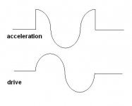
So a soundwave that a mic records and what we want the amp and driver to reproduce are not dependent on position? I argue that position x(t)=function of time is the fundamental parameter to measure because amplifier current drives voice coil position - I think they are a linear relationship and it is their nonlinearity that produces distortion. From position as function of time we can get velocity or acceleration. So we are trying to correct for the distortion by measuring position for error correction.
...
So we are trying to correct for the distortion by measuring position for error correction.
I would think so.
I rejected using an accelerometer for sensing because of the integration(s) required to get position.
It would be fine for sine wave vibration testing (which I did for 12 years in a test lab) but not for music! (IMHO)
I would like to see the results using a "burst" waveform using an accelerometer as feedback.
")
Attachments
http://www2.ece.ohio-state.edu/~schniter/pdf/subwoofer.pdf
I have built several as i stated before... its working wery well!
I have built several as i stated before... its working wery well!
http://www2.ece.ohio-state.edu/~schniter/pdf/subwoofer.pdf
I have built several as i stated before... its working wery well!
ESL,
Very nice paper - nice work man!
 Ohio State has some good stuff! My google search did not catch this and I am glad you pointed it out. This is exactly the info I was looking for. I am really surprised by how well the piezo accelerometer output tracks with SPL (Fig 3.3.1). What is the mass of the piezo element and can it be made small enough to work with a 4 inch full range driver with a typical Mms of 4 grams?
 Regards,
X
Counting fringes...yes...I would like to see the circuit to convert that to a linear signal.
It's a lot more convenient to process things digitally, then output the "final" analog version. In 1985, this took several large boards in a rack, these days, it's easily done in real time with a microcontroller and ADC/DAC.
You can use one extra voice coil as well...
But my experience is that a piezo tweeter works really really good!
http://www.macaulayaudio.co.uk/roaring%20sub.pdf
student project with accellerometer:
http://www.ti.com/corp/docs/landing/universityprogram/09_winners/Virginia_Tech_LaBella.pdf
Here is a study which is interesting.
Well i have some circuit design to share that works really good.
send me a PM
ESL,
Thanks for the link on the dual voice coil technique with one serving as the transducer. Very clever, but it only gives signal when there is motion - kind of like the accelerometer. It is nice because it is easy to fit an extra sensing coil in a driver as the sensing one doesn't need to have as many windings to produce drive power. I am surprised that there is not a commercial implementation of this yet. Or is there and I am not aware of it?
Thanks for the link on the dual voice coil technique with one serving as the transducer. Very clever, but it only gives signal when there is motion - kind of like the accelerometer. It is nice because it is easy to fit an extra sensing coil in a driver as the sensing one doesn't need to have as many windings to produce drive power. I am surprised that there is not a commercial implementation of this yet. Or is there and I am not aware of it?
Works great. Works on all woofing drivers. Simple. Coherent. No little gizmos with their own distortions to glue to the dust cap.There is also the bridge technique by getting the motion induced voltage from the voice coil (no second coil needed) and creating an error signal.
Anybody can mock-up a bridge and derive an error signal and see if they'd like to correct it.
Ben
A good question. Essentially, you don't.More info on the bridge technique please. How do you separate voltage from amp vs motion induced voltage?
If you read the signal across a small resistor in series with the driver, you are looking at the impressed voltage less driver static impedance, less the driver motional impedance (AKA back EMF).
Reading it in a bridge (balanced for static impedance (not really correct to call it DC resistance)), you remove the static component and the impressed signal and therefore enhance the motional component. See first diagram:
Patent US5542001 - Smart amplifier for loudspeaker motional feedback derived from linearization ... - Google Patents
The reason you don't see anything special eyeballing the final signal is because that's how feedback works. You take the whole final signal and subtract it from the source signal (way, way, upstream). The final signal doesn't look much different to your eyeball but when subtracted, the magic happens.
Back to your good question. So the problem is that it looks on the scope only wee bit different than the impressed voltage unless you have sky-high distortion in the driver. So you need to analyze it by removing the fundamental with a spectrum analyzer, distortion tester, XY plot, or what I used for many years, home-brew twin-tee filter.
I'm just an amateur and maybe others can do a better job clarifying.
Helpful?
Ben
Last edited:
Are you still looking for a way to sense the position of the cone directly?
Here is my idea to do this using an LED emitter of the right peak wavelength and several simple CdS photoresistor detectors. Place the LED on the underside of the cone near the VC former connection and position a "vane" or "light shield" a small distance away. Position the array of photoresistors so that at rest half of them have the LED light blocked by the vane. As the cone moves up and down the position of the edge of the shadow will change, and more or less total area of the photoresistors will be illuminated. The outputs from all photoresistors can be summed together to give a composite "total" voltage that will go up and down with cone position. This needs to be correlated with actual excursion, but should be linearly related. At maximum excursion at least part of one photoresistor must be exposed to the light source.
The photoresistors must overlap so that there are no zones where a change in the position of the shadow from the vane does not change the total summed output. This can be done by using two nesting columns of photodiodes, one positioned down by half the diameter of the photoresistor, like the ROWS in this image:
-Charlie
Here is my idea to do this using an LED emitter of the right peak wavelength and several simple CdS photoresistor detectors. Place the LED on the underside of the cone near the VC former connection and position a "vane" or "light shield" a small distance away. Position the array of photoresistors so that at rest half of them have the LED light blocked by the vane. As the cone moves up and down the position of the edge of the shadow will change, and more or less total area of the photoresistors will be illuminated. The outputs from all photoresistors can be summed together to give a composite "total" voltage that will go up and down with cone position. This needs to be correlated with actual excursion, but should be linearly related. At maximum excursion at least part of one photoresistor must be exposed to the light source.
The photoresistors must overlap so that there are no zones where a change in the position of the shadow from the vane does not change the total summed output. This can be done by using two nesting columns of photodiodes, one positioned down by half the diameter of the photoresistor, like the ROWS in this image:
An externally hosted image should be here but it was not working when we last tested it.
-Charlie
Charlie - yes, advantages to working with light but all kinds of mechanical complexity involved in your mask and matrix-board as well.
Do you suppose your matrix of photodetectors will have and order of magnitude less distortion (that is, will be more precisely linear) than a $200 woofer that is the product of 75 years of ardent development to make it linear?
On the other hand, easy to imagine capacitative sensors that only need to sense distance and the linearity resides in properties of the air gap!
Ben
Hi,
the problem with such photo-sensors would probabely be to achieve a sufficient dynamic range -or, the other way round- sufficient resolution.
T&A tried it with optical Sensors (kind of optical fork sensor) and a wedged or conical bezel fixed to the speaker dustcap, protruding through the magnet core to the inside of the casing. A hood shielded the structure against air pressure from the casings inside. Depending on the cones position the bezel shaded the sensors light source and such a signal proportonal to the displacement/position could be generated. They later omitted with this, probabely due to complexity and resolution issues.
Another method is to measure position with a very fine light-dot passing over a PSD (position sensing device) which is basically a flat light-sensitive resistor which detects the position of the dot over its sensing area. Again resolution/dynamic issues are seriously limiting factors.
jauu
Calvin
- Status
- This old topic is closed. If you want to reopen this topic, contact a moderator using the "Report Post" button.
- Home
- Loudspeakers
- Planars & Exotics
- Closed-Loop Amplification with Driver Cone Position Fedback